| Since | 21.0 |
This component sets up the neck and head controls for a character, and can be run in a loop over different segments, or parts, of the character.
The example in this file demonstrates how to use the neck rig component for the Otto test geometry.
This component is similar to the spline component and creates the controls shown in the image below. The tip control, root CV (control vertex), and tip CV can be translated and rotated, while the root, mid, and end controls can only be rotated.
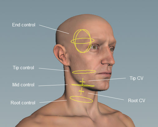
The controls are parented in the following hierarchy, with the root control as the parent of the hierarchy: root control → mid control → tip control → end control. By default, the CVs are parented to the closest outer control, so the root CV is parented to the the root control, and the tip CV is parented to the tip control:
The default position of the end control is higher up on the head, but its pivot position is at the middle of the head. You can change the end control position with the End Control Offset parameter.
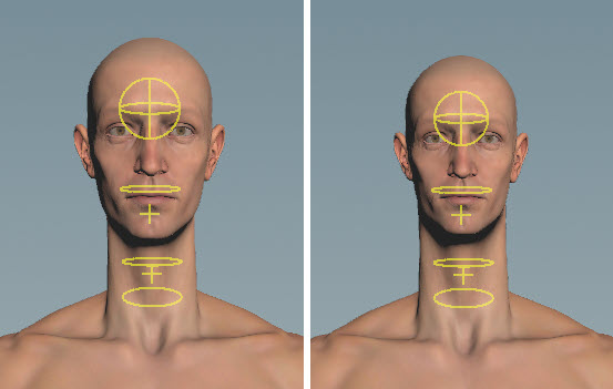
If you want to rotate the head only, use the end control. If you want to also have the neck twist with the head rotation, use the tip control:
Parameters 
Name
The name to add to the nodes created by this component. When using Segments, the segment name is also added to the node names.
Settings 
Curve Order
The number of control points used to construct the curve. By default, Curve Order is set to 4 because we have the following control points for the neck - the root control, root CV, tip CV, and tip control.
A Bezier curve (curve type is set in parameter Type) requires that the number of control points is equal to the curve order. Compound curves share a control point between their individual curve segments, so each additional curve segment requires an additional order-1 control points. This requirement can be expressed by the equation <number_of_control_points> % (order-1) == 1. See control spline for more information.
Pin Root
When turned on, constrains the orientation of the driven root to the controls. When turned off, the neck solver determines the orientation of the root.
Pin Tip
When turned on, constrains the orientation of the driven tip to the controls. When turned off, the neck solver determines the orientation of the tip.
Add Stretch Control
When turned on, adds a configuration parameter in the neck component’s ![]() menu that allows you to adjust the stretch of the neck:
menu that allows you to adjust the stretch of the neck:
Type
The type of curve to create from the control points.
Stretch
Specifies whether to keep the length of the neck. When set to 0, the neck keeps its length. When set to 1, the neck stretches to follow the tip control.
Stretch Scale
Controls the amount of stretch. Increasing this value increases the effect of the stretch.
Squash Scale
Controls the amount of squash. Increasing this value increases the effect of the squash.
Keep Tip Scale
When turned on, the scaling of the neck at the tip remains unchanged as you stretch the neck. When turned off, the neck at the tip is scaled as you stretch the neck.
Driven 
Segments
Segments are tags that separate each neck chain. Tags can be set up on skeleton joints using an ![]() Attribute Adjust Array SOP. See preparing skeletons for rigging for more information.
Attribute Adjust Array SOP. See preparing skeletons for rigging for more information.
If Segments is empty, the neck logic is run once.
Note
The Segments parameter does not take APEX path patterns, for example, the #<tag> function. Instead, specify the tag names directly in this field.
Driven
The ![]() TransformObject nodes to drive, for example,
TransformObject nodes to drive, for example, neck_01, neck_02, neck_03. This parameter also accepts APEX path patterns, so you can specify tags in this field, for example, #neck.
It’s good practice to also specify the bind tag that is set up by default on the FK transform component’s Tags parameter. The FK transform component is normally the first component used to start building a rig. Including the bind tag helps to ensure that you don’t include other controls that might have inherited, for example, the neck tag. So for this component, you can set Driven to “#bind & #neck”.
Driver 
By default, the neck component sets up a tangent neck with 6 controls - Root Name, Root CV Name, Mid Name, Tip CV Name, Tip Name, and End Name. Make sure the control names are unique and don’t conflict with any other controls.
To avoid naming conflicts when creating multiple neck setups, you can specify the neck segment using the string “{segment}”. For example, if your segment is named neck_01 (Segments is set to neck_01), you can set Root Name to {segment}_root_ctrl. The value of Segments replaces the string “{segment}”, so the root control is named neck_01_root_ctrl.
Custom
When turned on, creates the number of controls specified in Num Controls.
Num Controls
When Custom is turned on, this is the number of controls to create.
Root Name
When Custom is turned off, this is the name of the root control.
Root CV Name
When Custom is turned off, this is the name of the root tangent CV.
Tip CV Name
When Custom is turned off, this is the name of the tip tangent CV.
Tip Name
When Custom is turned off, this is the name of the tip control.
Mid Name
When Custom is turned off, this is the name of the middle control.
End Name
When Custom is turned off, this is the name of the head control. This control doesn’t affect the neck.
CV Root Offset
The offset to add to the root tangent CV.
CV Tip Offset
The offset to add to the tip tangent CV.
End Control Offset
The offset to add to the end control.
Scale Inheritance
Sets the scale inheritance of the neck controls.
Promote T
When turned on, promotes the translate component of the neck controls.
Promote R
When turned on, promotes the rotate component of the neck controls.
Promote S
When turned on, promotes the scale component of the neck controls.
Parent 
Root
The parent of the root control. If left empty, the root control is parented to its associated ![]() TransformObject node’s parent. For example, if the root control sits at node
TransformObject node’s parent. For example, if the root control sits at node C_neck_02, and C_neck_02's parent is C_neck_01, then the root control will be parented to C_neck_01 if this parameter is empty.
You can also set parent tags on the skeleton, and use the parent tag plus the Segments tag to get the parent for each segment. For example, if your segment is named spine (Segments is set to spine), and you tag the parent joint with spine_parent, then you can set Root to {segment}_parent. The value of Segments is used to replace the string “{segment}”.
To unparent the root control, set this parameter to an underscore (“_”).
This parameter accepts APEX path patterns, so you can specify tags in this field, for example, #<tag>.
Tip
The parent of the tip control. If left empty, the tip is parented to the Root. To unparent the tip control, set this parameter to an underscore (“_”).
This parameter accepts APEX path patterns, so you can specify tags in this field.
CV
The parent of the CVs. If left empty, the CVs are parented to the closest outer control. To unparent the CV controls, set this parameter to an underscore (“_”).
This parameter accepts APEX path patterns, so you can specify tags in this field.
Tags 
Component
The tags to add to the neck node (![]() rig::SplineInterpolateTransforms) created by this component.
rig::SplineInterpolateTransforms) created by this component.
Root
The tags to add to the root control ![]() TransformObject nodes created by this component.
TransformObject nodes created by this component.
Tip
The tags to add to the tip control ![]() TransformObject nodes created by this component.
TransformObject nodes created by this component.
CV
The tags to add to the CV ![]() TransformObject nodes created by this component.
TransformObject nodes created by this component.
Shape 
Shape
The shape of the controls. It can be set to any of the built-in APEX control shapes.
Color
The color of the control shapes. To inherit the shape color from the skeleton, set this value to (0, 0, 0).
Translate
The translation of the control shapes.
Rotate
The rotation of the control shapes.
Scale
The scale of the control shapes. To inherit the shape scale from the skeleton, set this value to (0, 0, 0).
| See also |