| On this page |
-
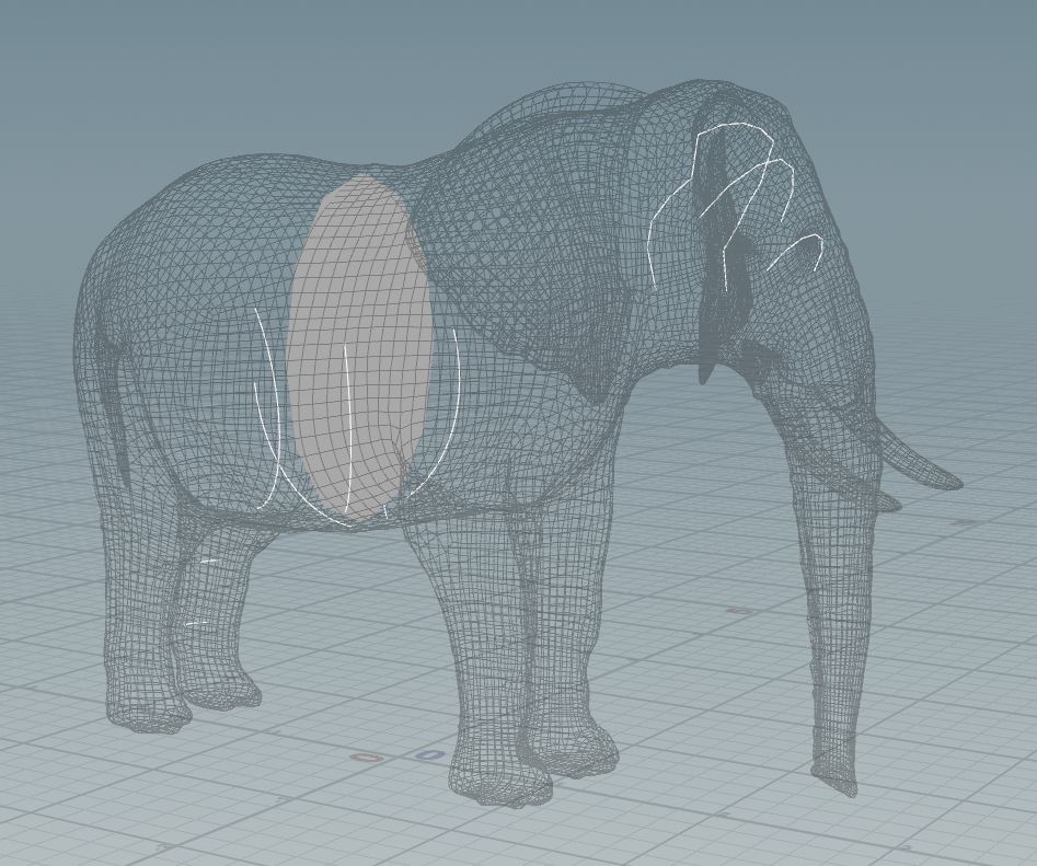
In the Network Editor, model your geometry objects to use as capture shapes in-context at their world space positions inside the volume of the character. Only the points of the capture geometry inside of the volume are considered for the biharmonic calculations.
Warning
Only use polygonal geometry for your control shapes. Nurbs do not work properly.
-
To change the shape or size of the world space shapes you created, use common SOP nodes such as the
 Edit SOP or
  Transform SOP to modify them.
Creating a capture geometry library 
-
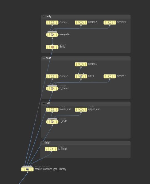
Once you have created your capture geometry shapes, create a
 Merge Packed SOP node.
 -
Connect all the capture geometry shapes to the Merge Packed SOP node.
-
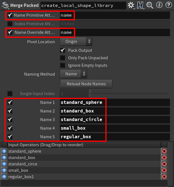
In the Merge Packed SOP node’s parameters:
-
Turn on the Name Primitive Attribute and Name Override Attribute parameters. This allows you to define new names for your capture geometry shapes.
-
Use the Name parameters to specify meaningful names for all the capture geometry shapes. For example,
wrist_leftorhips_tilt. You should name your shapes properly to make them easier to identify later.
Warning
After you have assigned your shapes in the Attach Joint Geometry SOP node, do not click the Reload Node Names button on the Merge Packed SOP node. This invalidates all your shape-joint assignments by reverting all the control shapes' names to their defaults.
-
-
After you set your capture geometry library, create the
 Attach Capture Geometry SOP node.
 -
Connect the capture pose output from your character’s import node to the first input on the Attach Joint Geometry SOP, and then connect the Merge Packed SOP node’s output to the second input (shape library input) on the Attach Joint Geometry SOP node.
-
Make sure to set the Role to Capture Geo.
You can now assign your capture geometry shapes to your character’s joints.
Assigning a capture geometry shape to a joint 
You can assign a capture geometry shape to a joint in your input skeleton to link it to the joint and designate the shape as the joint’s new capture object.
-
Choose the
Attach Joint Geometry SOP node, click the viewport, and press Enter. You are now in the viewport state. -
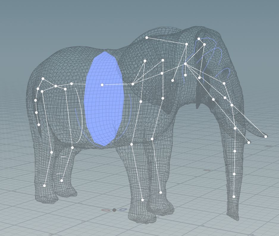
In the viewport state’s toolbar, choose Mode ▸ Assign Shapes to set the interaction mode to shape assignment and turn on Assign in World Space.

Assign Shapes and Assign in World Space modes and in the Attach Joint Geometry viewport state toolbar The world space shapes appear as light blue in the viewport state.
-
In the viewport state, click the joint in your skeleton you want to assign the world space shape to as a control, press-hold G, and then LMB-click the world space shape you want to assign to the joint.
In the Parameter Editor, a new Assign Shapes multiparm for the joint appears in the Add Shapes parameters tab.
In the Assign Shapes multiparm, your selected joint appears in its Group field, the capture geometry shape you clicked appears in the Shape Name field, and the Keep Shape World Transform parameter is turned on.
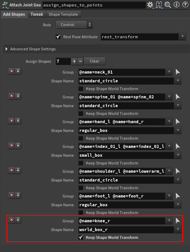
New Assign Shapes multiparm for a world space shape And a blue ring appears around the joint indicating that it now has an active Assign Shapes multiparm.

Blue ring that indicates the joint has an Assign Shapes multiparm Tip
Alternatively, you can create a new Assign Shapes multiparm by either clicking the Create New Group button in the viewport state toolbar or manually adding the multiparm in the Parameter Editor.
The capture geometry shape you chose in the Shape Name parameter field is now assigned as the control for the joint listed in the Group field.
The world space shape’s position (in world space and relative to your character) does not change.
Tip
-
If you need to remove a joint from a shape assignment, ⌃ Ctrl - LMB click the joint in the viewport state.
-
If you need to re-assign a joint to a new multiparm, you can choose the joint and press G again. The joint is automatically removed from its old multiparm and added to a new one.
Shape templates 
You can use the template input for an auto assignment if the names match your capture geometry library and the joints you want to assign.
-
Create a
 Attribute Promote SOP node and connect its input to the output of your shape library’s Merge Packed SOP node.
 -
In the Attribute Promote SOP node, set the Original Name attribute to the network to name and set the Original Name attribute to Primitive. Additionally toggle the Original Name attribute off.
-
Connect the output of the the Attribute Promote SOP to the third input of the
Attach Joint Geometry SOP node -
Choose the Attach Joint Geometry SOP node.
-
In the Parameter Editor, choose the Shape Template tab and then configure its parameters for how the shape template transfers to your character and the shapes match to its joints.
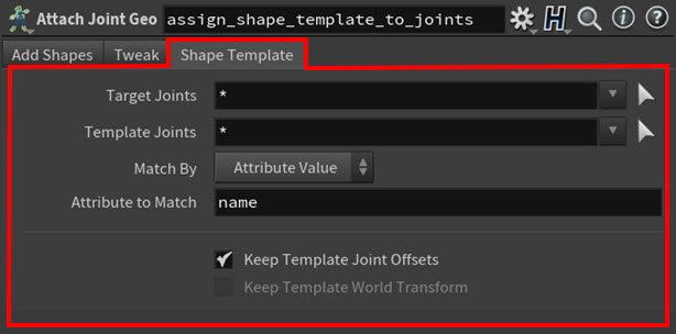
Shape Template tab parameter example for mirroring -
Use the Target Joints parameter to determine which joints get a template assignment.
-
Use the Template Joints parameter to determine which control shapes get assigned to the skeleton.
-
Use the Match By parameters to determine how to match the shape template to your skeleton.
-
Use Attribute Value (the default setting) to match based on point name attribute values on the skeleton and the shape template.
-
Turn on Keep Template World Transform to keep the world positions of your shapes from your capture geometry library.
-
Mirror capture geometry shapes 
-
Create a
 Delete Joints SOP node and connect its input to the output of your Attach Capture Geometry SOP node.
 -
Use the Group to isolate the joints of the body side you want to mirror your shapes.
-
Create a
 Skeleton Mirror SOP node and connect its input to the output of your Skeleton Mirror SOP node.
 -
Adjust the parameters of the Skeleton Mirror SOP node based on the specifics of your skeleton. Make sure the Replace Tokens match the prefix or suffix handling of your original skeleton.
-
Create a
Attach Capture Geometry SOP node and connect its third input to the output of your Skeleton Mirror SOP node. Connect the first input of the new Attach Capture geometry SOP node to the output of the original Attach Capture geometry SOP node -
In the Parameter Editor, choose the Shape Template tab and use its parameters to configure how transfer the mirrored shapes to your original skeleton.
-
Use the Target Joints parameter to choose the joints of the body side you want to assign the new mirrored shapes.
-
Use the Template Joints parameter to choose the joints of the body side you want to assign the new mirrored shapes.
-
Use Attribute Value (the default setting) to match based on point name attribute values on the skeleton and the shape template.
-
Turn on Keep Template World Transform to keep the world positions of your shapes from you capture geometry library
-
Apply the capture shapes to the capture process 
-
Create a
 Joint Capture Biharmonic SOP node and connect its second input to the output of your Attach Capture Geometry SOP node
 -
Connect the first input with the geometry you want to be captured and optionally the third input with an animated skeleton for reference
-
In the Parameter Editor, set the Role to the role set by the Attach Capture geometry SOP node. The capture geometry is automatically used for the solve of the biharmonic capturing. You can bypass it via the Use Capture geometry Joints toggle
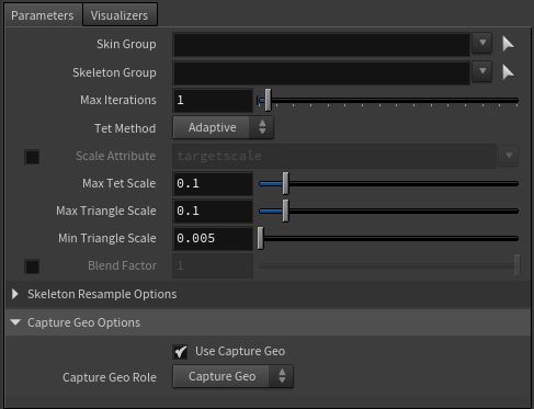
Parameters for the Joint Capture Biharmonics SOP using capture geometry