primary
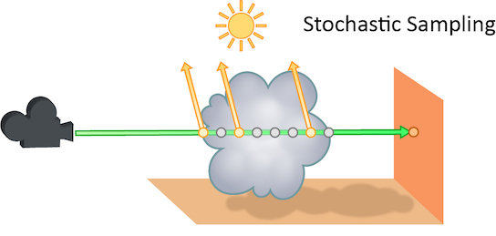
Rays sent from the camera
| On this page |
These properties control rendering in Karma. They can be set with different LOP nodes in Solaris, according to their application. Karma settings nodes usually have the easiest interface for setting render properties. More generic nodes will have a karma folder tab available in the parameter interface.
| Global |
|
|
| Object |
|
|
| Light |
|
|
| Camera |
|
For advanced users, to get a complete list of all properties defined in Karma, you can run the karma --all-properties on a command line. This will print a JSON-formatted string to stdout.
Warning
Any undocumented properties may change at any time and may not be fully supported.
Cancel Render on Missing Texture
Turning on this option will cause Karma to stop the render with an error if it encounters a missing texture map.
Cancel Render on No Working GPU Devices
Turning on this option will cause Karma to stop the render with an error if no working gpu devices are discovered.
As rendering progresses, print out progress using the Alfred progress format. For multi-frame renders, this progress will be cumulative across frames (i.e. if there are 4 frames, percent complete will be 25% after the first frame finishes).
If there are no lights in the scene, a headlight is created by default. To disable, turn off this checkbox.
Specifies a camera that is used for dicing complicated surfaces. This can provide consistent dicing of surfaces when the viewing camera is moving.
Select the rendering engine.
CPU
Runs entirely on the CPU. Since this engine is entirely in software, it will generally have more features and more correct output, however it is much slower than the XPU engine.
XPU
The XPU engine uses available CPU and GPU (graphics card hardware) resources. Since this engine inherits the limits of what can be done on a GPU, it will generally lag behind the CPU engine in features, however it is much faster than the CPU engine.
A whitespace-separated list of shading component names that will be computed for export. If you have defined new component labels in your materials, these can be added to the list so that they are exported for per-component export planes. If you are not using some components, remove them from the list to improve render efficiency.
PBR light exports assume that this list is complete - that is, all components created by shaders are listed. If there are unlisted components, light exports may be missing illumination from these components.
A space-separated list of component types that will behave like diffuse bounces. This will affect which reflection scope is used based on the ray type and also which bounce limit to use. Uncategorized component types are assumed to be reflections.
A space-separated list of component types that will behave like refract bounces. This will affect which reflection scope is used based on the ray type and also which bounce limit to use. Uncategorized component types are assumed to be reflections.
A space-separated list of component types that will behave like volume bounces. This will affect which reflection scope is used based on the ray type and also which bounce limit to use. Uncategorized component types are assumed to be reflections.
A space-separated list of component types that will behave like subsurface scatter bounces. This will affect which reflection scope is used based on the ray type and also which bounce limit to use. Uncategorized component types are assumed to be reflections.
Override lighting in the scene. There are several options:
Off: Use the lighting as defined on the USD stage
Emissive Objects: Disable all light sources so that only emissive objects (geometry lights) are enabled.
Headlight: Disable all light sources and create a headlight
Dome Light: Disable all light sources and create a dome light
Disable all lighting and material evaluation, using only the display color to shade primitives.
When rendering in headlight mode with ambient occlusion shading, this distance is used for occlusion testing. Smaller values will result in faster, but less accurate shading.
When rendering in headlight mode, perform this many ambient occlusion samples per shade.
The near/far distance for depth cue fog when lighting is disabled. If the far distance is less than the near distance, fog will be disabled.
When set to Path Traced, maximum of 1 indirect ray is generated per bounce. When set to Automatic, the number of indirect rays is calculated based on initial noise estimate, target noise threshold, and the maximum number of camera rays. Also note that under Automatic mode, number of samples for direct lighting is adjusted based on noise estimate as well.
Depth at which indirect rays start to get stochastically pruned based on ray throughput.
Constrain by Maximum Roughness
Roughness parameter in GGX BSDFs are clamped by the maximum roughness value propagated down the ray chain in pathtracing. Enabling this option can cut out a lot of noise in indirect specular (in particular, cases where glossy surface is reflected by a rough specular surface) at the cost of a bit of accuracy.
A multiplier on the shading quality. This is used for texture and area evaluations in shading.
When rendering to the Solaris viewport, this causes each render to start with a new random seed.
The initial bucket size for IPR rendering.
As buckets are rendered, the coarse bucket size decreases. This specifies the bucket size at which Karma runs the de-noising filter on the image.
When rendering in IPR mode, reserve this number of threads for other Houdini tasks.
Image filters post-process the filtered pixels to produce the final image. This parameter takes a string containing a JSON-encoded list of filters and their arguments. Usually you don’t need to craft this value by hand, it’s computed by the Karma LOP from the values of filter-related parameters. See Karma filters for more information.
Specifies the distribution of samples over pixels. A box filter will distribute samples randomly over the interior of each individual pixel. A Gaussian filter will distribute samples in a disk around the pixel center, but with a Gaussian distribution (instead of a uniform distribution).
This is the size of the Pixel Filter. A Gaussian filter with a filter size of 1.8 will be slightly less blurry than a Gaussian filter with a filter size of 2.0.
When rendering, a Pixel Oracle tells karma which pixels need additional sampling and which pixels are converged. This parameter tells karma which oracle to use.
uniform
Uniformly distribute rays to each pixel. Each pixel will always get the same number of ray-samples.
variance
Distribute rays based on variance in the rendered image.
JSON list of image filters specifically for background image preview and slap-comp of shadows and other holdout elements.
“Off” disables Background IPR Filter. “Auto” enables it only for IPR. “On” enables it for both IPR and off-line rendering.
Whether to use a fixed size cache (karma:global:cachesize) or whether to use a proportion of physical memory (karma:global:cacheratio)
The proportion of physical memory Karma will use for its unified cache.
For example, with the default vm_cacheratio of 0.25 and 16 Gb of
physical memory, Karma will use 4 Gb for its unified cache.
The unified cache stores dynamic, unloadable data used by the render including the following:
2D .rat texture tiles
3D .i3d texture tiles
3D .pc point cloud pages (when not preloaded into memory)
Note: This value is only used for off-line rendering, not IPR.
An explicit memory limit for the unified shading cache. This is deprecated in favor of using the Cache Memory Ratio.
Note: This value is only used for off-line rendering, not IPR.
Normally, geometry settings specified in the render settings LOP provide default values for objects. Each object can override the value of the default.
This parameter specifies a pattern of object property names whose values
will taken from the render settings, overriding any per-object settings.
For example, setting the pattern to diffuselimit will override the
diffuse limit for all objects with the value specified on the render
settings LOP.
The minimum distance used when testing if secondary rays from a surface intersect with other objects in the scene. The distance is measure from surface along the direction of the ray. Objects within the ray bias distance are ignored.
This is the region of the image that will be rendered. If the region is smaller than the full image, the data window will act as a crop region. If the data window is larger than the full window, the data window will act as overscan rendering. The data window is specified in pixels.
Most pixels are square. However, some display devices have non-square pixels. This option specifies the pixel aspect ratio.
Sample filters are used to modify samples before they are sent to pixel filters.
This parameter specifies a list of filters. These filters are specified as a JSON list.
The number of ray-samples sent through each pixel. More samples will result in a less noisy image. “”Pixel Samples“ and ”Primary Samples" are the same.
The number of ray-samples sent through each pixel when using the path traced convergence mode. More samples will result in a less noisy image.
If you turn this off, Karma still calculates velocities (and the velocities can be stored in an AOV), but it sends all camera rays at shutter open, so the image will not have any apparent motion blur. This may be useful if you simply don’t want any motion blur to create a certain visual effect.
The number of transparent samples to be shaded as a ray travels through partially opaque objects. Increasing this value will result in less noise in partially opaque objects and is generally less costly than increasing Pixel samples, Volume Step Rate, or Min and Max ray samples. This parameter will not have any effect on noise from Indirect Sources however.
Whether Karma should perform uniform sampling of lights or whether rendering should use the light tree. The light tree can be significantly faster for scenes that have large numbers of lights.
Some lights cannot be added to the light tree, and will all be sampled by Karma:
Dome Lights
Distant Lights
Point Lights
Lights with Light Filters
Lights with shaping controls (i.e. spot lights)
This is a global control to improve sampling quality for all lights. This acts as a multiplier on the individual light quality controls. Increasing the quality will improve direct light sampling as well as shadows/occlusion.
Karma breaks down an image into multiple buckets for rendering. This is the side length (in pixels) of the square bucket. The default is 32, specifying a 32 pixel x 32 pixel bucket. Threads operate at the bucket level, so it might be useful to lower the bucket size if there are only a few buckets that are particularly expensive. That way the expensive areas can be divided across more threads.
For example, if the image is mostly empty, but there’s a distant object that fits within single 32 x 32 bucket, then that object will only be rendered using 1 thread. If you switch to a 16 x 16 bucket, then the object might be split across 4 buckets and have 4 threads working on it.
Ideally changing the bucket size doesn’t change the results, but Karma measures variance across pixels within the current bucket, so if you set it to a low value, for example 4, Karma only has 4 x 4 = 16 pixels to look at, so Karma will tend to make very poor variance estimates. This can show up as black pixels, where pixel rendering terminated prematurely due to a bad variance estimate.
Specifies which buckets are rendered first. Values can be:
middle
Buckets start from the middle of the image.
top
Buckets at the top of the image are rendered first.
bottom
Buckets at the bottom of the image are rendered first.
left
Buckets at the left side of the image are rendered first.
right
Buckets at the right side of the image are rendered first.
Note
When rendering to Mplay, the user can click to focus on an area to render. Click to focus is not available with Enable Indirect Guiding turned on.
Determines how the image will be rendered.
progressive
The entire image will be progressively rendered, so the whole image resolves at the same time. This mode gives you a sense of what the whole image will look like without waiting for the render to complete.
bucket
Each bucket renders to completion before advancing to the next bucket. This mode lets you see what the final quality will be like without waiting for the whole image to render. This mode isn’t available with Enable Indirect Guiding turned on.
Note
When rendering for IPR, Karma will use progressive rendering until the IPR preview passes are complete.
When rendering in bucket mode (see imagemode), this is the number of progressive passes over the image to perform before switching to bucket mode.
When rendering in IPR mode, this setting controls whether Karma will re-dice displacements and sub-division surface when the view transform changes. Continuous re-dicing of geometry can add significant time to start-up time for the render, but will provide more accurate results.
This parameter controls the shading quality scale factor for geometry that is not directly visible to the camera. For geometry that is outside the field of view (i.e. visible only to secondary rays), karma will smoothly reduce the shading quality based on the angle between the geometry and the edge of the viewing frustum. Smaller values can increase performance particularly in scenes where the camera is within the displacement bound of nearby geometry, where it permits the hidden primitives to be diced more coarsely than those that are directly visible.
The maximum value a shading sample is allowed to contribute to an LPE image plane to reduce appearance of “fireflies” caused by undersampling of extremely bright light sources. Note that reducing this value can result in an overall reduction in the amount of light in your scene.
Color limit applied to indirect bounce only. Note that this parameter is ignored unless Shared Color Limit is turned off.
When turned on, indirect bounces use Color Limit value and Indirect Color Limit parameter is ignored.
When turned on, Karma does a pre-render to roughly estimate of the light in the scene, and uses that to guide indirect diffuse rays, rather than just relying on the BSDF sampling distribution. This can improve “difficult” lighting (for example, caustics, and mostly indirect lighting), but can make “easy” lighting noisier. Before using this, you can try rendering direct and indirect AOVs to see where the noise is. If the noise is mostly caused by the direct lighting, there’s no point in turning on path guiding.
Note
When rendering to Mplay, the user can click to focus on an area to render. Click to focus is not available with Enable Indirect Guiding turned on.
Number of pixel samples to use for prepass render when Indirect Guiding is turned on. Recommended minimum is 10% of pixel samples under Path Traced convergence mode, or the same number of pixel samples under Automatic convergence mode. Grid-like artifacts can show up in the final render when this value is too low and not enough data is collected. It’s recommended to keep this value above 64.
Indirect Guiding Spatial Filter
Applies blur to spatial component of path guiding samples while training. Can be increased to reduce grid-like artifacts at the cost of efficiency.
Indirect Guiding Directional Filter
Applies blur to directional component of path guiding samples while training. Can be increased to reduce grid-like artifacts at the cost of efficiency.
Object ID for the object that will be unwrapped for texture baking. Texture baking will look for the objects in the scene that have the corresponding object ID per type (low resolution, cage and high resolution) and assigns them accordingly. There should only be one object per type
Tile number that this scene will be texture baking. For UDIM texture baking this is the UDIM index (between 1001 and 9999). For PTEX texture baking, faces are laid out onto paginated grids ordered from largest to smallest area. The tile number refers to which page is being baked currently.
Texture Baking PTex Minimum Resolution
Minimum resolution of a single PTex face when doing PTex texture baking.
Texture Baking PTex Maximum Resolution
Maximum resolution of a single PTex face when doing PTex texture baking.
Texture Baking PTex Small Face Percent
Used with PTex relative scaling. Refers to how many quads should approximately have resolutions less than the minimum resolution in relative scaling. This value is only an estimate based on the approximate lengths/widths of each face.
Texture Baking PTex Relative Scaling
Used to enable relative scaling for PTex. Relative scaling attempts to adjust the resolution of the PTex faces rendered based on the size of the meshes and the Texture Baking Small Face Percent. Relative scaling will adjust the minimum resolution so that a percent of the faces have less resolution than this minimum. This percent is the Texture Baking Small Face Percent
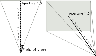
Width of the visible field.
Note
The correct aperture width for Super 35 mm format motion picture film is 24.89.
The type of projection mode, either perspective, orthographic, or custom CVEX lens shader.
USD represents the camera exposure as a logarithmic base-2 adjustment. So, in USD, a value of 0.0 has no effect, while a value of 1.0 will double image-plane intensities and a value of -1.0 will halve them.
The shutter time refers to the portion of a frame the shutter is actually open. On a physical camera, this if often referred to as Shutter Speed. The renderer uses this determine motion blur. The value should be in the range [0,1].
A value of 0 for the shutter time would mean that there is no motion blur at all, as the shutter is only “Open” for an instant. A value of 1 on the other hand would mean that the shutter is open for the entire length of the frame.
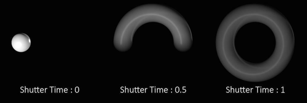
In the above example the sphere is rotating a full 360 degrees over the course of a single frame. You can see how the length of the “motion trail” or “blur” changes based on the shutter time. In most cases, the default value of .5 is appropriate for animated sequences and a good match for real world settings.
Keep in mind that this parameter controls the amount of time within a single frame, that the shutter is open. It does not refer to how long an individual frame is. To adjust the frame rate, change the Frames per Second parameter in the Global Animation Options.
The lens focal distance and distance from the camera at which objects will be in focus. This is only used when rendering using depth of field. Objects outside this distance will be blurred.
Lens fstop. This is only used when rendering using depth of field. Determines blurriness of depth of field effects.
Defines a VEX shader to be used for light evaluation. If the string is empty, the value will be taken from the HOUDINI_VEX_DEFAULT_LIGHTSURFACE configuration variable.
Whether the light intensity should be normalized based on the size of the area light.
The dimensions of the area light. This has different meaning depending on the light type:
Sphere Light
The first value specifies the radius of the light. The second value is ignored.
Rectangular Light
The first value specifies the width, the second specifies the height.
Disk Light
Cylinder Light
Line Light
For distant lights, this is the size of the light in degrees. The larger the angle, the softer the shadows. As an example, the sun is approximately 0.53 degrees when seen from the earth.
Controls the type of attenuation on the light source in the default light
shader. This may be:
none
No attenuation
half
Half distance attenuation
physical
Physically correct attenuation
The distance from the light at which Half Distance Attenuation produces half the light intensity.
As point lights get closer to geometry, the attenuation equation causes the
intensity of lights to go to infinity (a singularity caused by the division
by the distance between the light and the surface). Increasing this value
to something larger than zero creates an artificial buffer zone to prevent
the light from going to infinity. If the radius is set to 1, the brightest
value for the point light will be twice the intensity specified on the
light. If the value is 1.4142 (sqrt(2)), the brightest value will be the
intensity specified.
For distant geometry, there should be very little change in the intensity.
Artificially clamp the illumination distance from the light. Outside this radius, the light will have no effect.
The color of shadows for the light. This defaults to black. Setting the color to white (1,1,1), means the light will not cast shadows.
This value can be used to limit shadow tests to a specific distance. For example, with a dome light, setting the shadow distance to a smaller value will limit shadow tests to only nearby objects.
Controls whether multiple importance sampling will sample from the BSDF, the light, or both the BSDF and light.
This is the per-light sampling quality, that acts as a multiplier on the global Light Sampling Quality. Increasing the quality will add additional samples for this light source, improving the sampling quality of this light relative to other light sources.
When an object is used as a geometry light source, this sets the per-light sampling quality. Increasing the quality will add additional samples for this light source, improving the sampling quality of this light relative to other light sources.
Note: This is not the quality of light received by an object.
Any object with an emissive material will generate light within the scene. If an object is significant enough (e.g. size, brightness, etc…) then it is possible for Karma to treat that object as if it were an explicit light source (similar to regular lights), meaning the emitted light will be handled much more efficiently. But doing so will add extra overhead elsewhere in the system (e.g. increased memory usage, slower update times, etc…).
There are three options. “No” will set the object as not being a light source. “Yes” will set the object as being a light source. “Auto” (default) means Karma will use an internal heuristic to decide if the object should be treated as a light source.
Light Source Diffuse Multiplier
A multiplier for the effect of this emissive object on the diffuse, SSS, and volume response of materials
Light Source Specular Multiplier
A multiplier for the effect of this emissive object on the reflection and refraction response of materials
Controls the visibility of an object to different types of rays using a category expression. This parameter generalizes the Phantom and Renderable toggles and allows more specific control over the visibility of an object to the different ray types supported by karma and VEX.
primary
Rays sent from the camera
shadow
Shadow rays
diffuse
Diffuse rays
reflect
Reflections
refract
Refractions
For example, to create a phantom object, set the expression to “-primary”. To create a not renderable object, set the expression to the empty string “”. These tokens correspond to the string given to “raystyle” in the VEX trace() and gather() functions.
When using the light tree for rendering, Karma will try to put any light source that’s compatible into the tree. This option can force a light to be excluded from the tree and subject to uniform sampling, which can sometimes yield an improved sampling quality the light at the expense of speed.
If an environment map is larger than this resolution, it will be scaled down when performing texture analysis. If the map has some very small, very bright values, this filtering may affect how sampling of the environment map is performed.
A multiplier for the effect of this light on the diffuse, SSS, and volume response of materials
A multiplier for the effect of this light on the reflection and refraction response of materials
Custom label assigned to lights or objects for use with light path expression.
Controls whether the dome light is more likely to sample from the environment map or the portal geometry. For high-contrast HDRI with strong light sources, it may be beneficial to sample more from the environment map (set it less than 0), and for low-contrast/flat HDRI, the opposite may be true (set it greater than 0). Leave it at 0 for balanced approach.
If a light exists to add new light source instead of trying to replicate lighting in the live action plate, turn on this parameter so that its effect on background holdout geometry shows up in indirect bounces and its contribution to shadow holdout AOVs is omitted.
Whether to turn on motion blur. Changing this in the display options will require a restart of the render.
Instead of choosing the motion samples explicitly, Karma can also choose the motion samples based on the samples authored on the USD stage. This option will choose just the right number of samples to capture the motion described on the stage.
This setting applies to both transform and deformation motion samples for both geometry and instances.
Note: If the samples on the stage don’t align with the shutter times on the camera, it’s possible there will be some minor interpolation issues over the first and last segments (since motion will be truncated rather than interpolated).
This parameter lets you choose what type of geometry velocity blur to do on an object, if any. Separate from transform blur and deformation blur, you can render motion blur based on point movement, using attributes stored on the points that record change over time. You should use this type of blur if the number points in the geometry changes over time (for example, a particle simulation where points are born and die).
If your geometry changes topology frame-to-frame, Karma will not be able to interpolate the geometry to correctly calculate Motion Blur. In these cases, motion blur can use a velocities and/or accelerations attribute which is consistent even while the underlying geometry is changing. The surface of a fluid simulation is a good example of this. In this case, and other types of simulation data, the solvers will automatically create the velocity attribute.
Note
In Solaris, velocities, accelerations, and angularVelocities attributes are equivalent to v, accel, and w in SOPs, respectively.
No Velocity Blur
Do not render motion blur on this object, even if the renderer is set to allow motion blur.
Velocity Blur
To use velocity blur, you must compute and store point velocities in a point attribute velocities. The renderer uses this attribute, if it exists, to render velocity motion blur (assuming the renderer is set to allow motion blur). The velocities attribute may be created automatically by simulation nodes (such as particle DOPs), or you can compute and add it using the ![]() Point velocity SOP.
Point velocity SOP.
The velocities attribute value is measured in Houdini units per second.
Acceleration Blur
To use acceleration blur, you must compute and store point acceleration in a point attribute accelerations. The renderer uses this attribute, if it exists, to render multi-segment acceleration motion blur (assuming the renderer is set to allow motion blur). The accel attribute may be created automatically by simulation nodes, or you can compute and add it using the ![]() Point velocity SOP.
Point velocity SOP.
When Acceleration Blur is on, if the geometry has a angular velocity attribute (w), rapid rotation will also be blurred. This should be a vector attribute, where the components represent rotation speeds in radians per second around X, Y, and Z.
When this is set to “Velocity Blur” or “Acceleration Blur”, deformation blur is not applied to the object. When this is set to “Acceleration Blur”, use the karma:object:geosamples property to set the number of acceleration samples.
velocities) to do linear motion blur.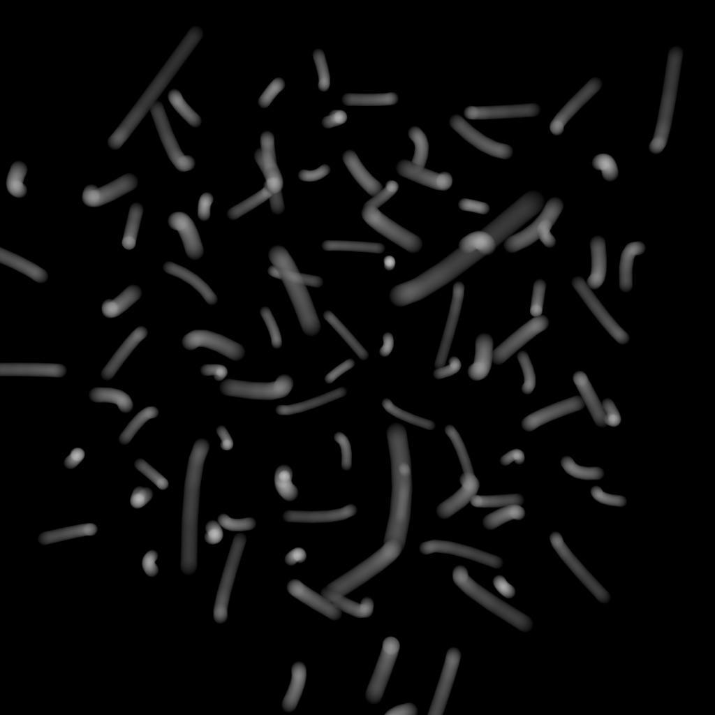
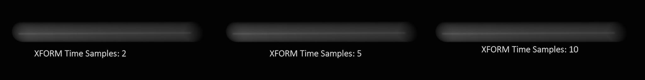
The number of sub-frame samples to compute when rendering deformation motion blur over the shutter open time. The default is 1 (sample only at the start of the shutter time), giving no deformation blur by default. If you want rapidly deforming geometry to blur properly, you must increase this value to 2 or more. Note that this value is limited by the number of sub-samples available in the USD file being rendered. An exception to this is the USD Skel deformer which allows.
“Deformation” may refer to simple transformations at the Geometry (SOP) level, or actual surface deformation, such as a character or object which changes shape rapidly over the course of a frame.
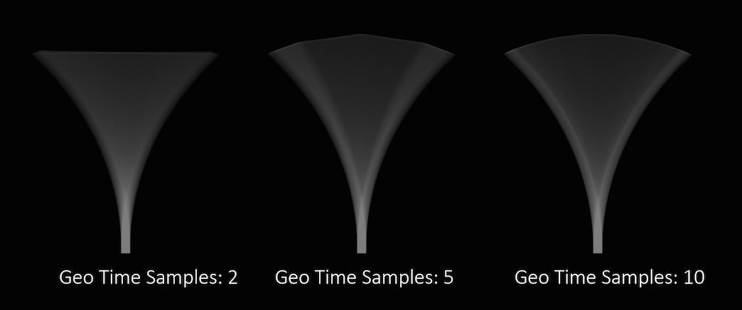
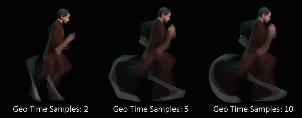
Objects whose deformations are quite complex within a single frame will require a higher number of Geo Time Samples.
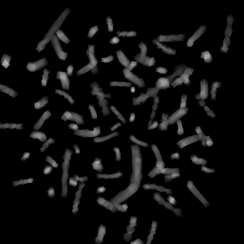
Deformation blur also lets you blur attribute change over the shutter time. For example, if point colors are changing rapidly as the object moves, you can blur the Cd attribute.
Increasing the number of Geo Time Samples can have an impact on the amount of memory Karma uses. For each additional Sample, Karma must retain a copy of the geometry in memory while it samples across the shutter time. When optimizing your renders, it is a good idea to find the minimum number of Geo Time Samples necessary to create a smooth motion trail.
Deformation blur is ignored for objects that have Velocity motion blur turned on.
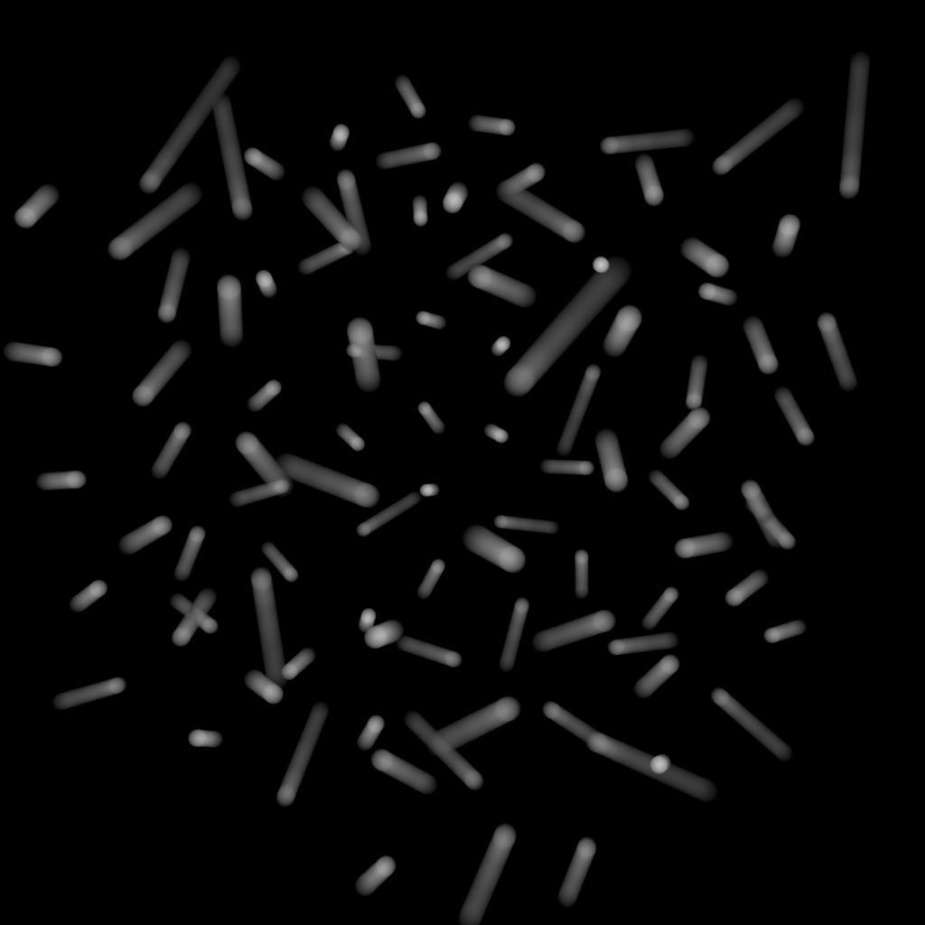
The number of samples to compute when rendering transformation motion blur over the shutter open time. The default is 2 samples (at the start and end of the shutter time), giving one blurred segment.
If you have object moving and changing direction extremely quickly, you might want to increase the number of samples to capture the sub-frame direction changes.
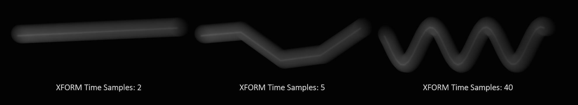
In the above example, it requires 40 transformation samples to correctly render the complex motion that occurs within one frame. (This amount of change within a single frame is very unusual and only used as a demonstration.)
Transformation blur simulates blur by interpolating each object’s transformation between frames, so it’s cheap to compute but does not capture surface deformation. To enable blurring deforming geometry, increase karma:object:geosamples.
When defining motion blur on instances, the transform of each instance can be blurred in addition to any motion blur occurring on the prototype. This option controls how the instance will compute the motion blur of the transform on each instance. For example, when instancing prototypes to a particle system, you'd likely want to use velocity blur to compute motion blur (the transform on the prototype would be blurred by the velocity on the particles).
No Velocity Blur
Use deformation blur of the instance to compute the blur on the transform.
Velocity Blur
To use velocity blur, the instance must be a point instancer with velocity attributes on the points.
The velocities attribute value is measured in Houdini units per second.
Acceleration Blur
To use acceleration blur, the instance must be a point instancer with point velocities and acceleration values. The renderer uses this attribute, if it exists, to render multi-segment acceleration motion blur (assuming the renderer is set to allow motion blur). The accel attribute may be created automatically by simulation nodes, or you can compute and add it using the ![]() Point velocity SOP; this will be converted to
Point velocity SOP; this will be converted to accelerations when the SOP geometry is converted to USD.
When motion blur on instances is computed using Acceleration Blur or Deformation Blur, this parameter specifies the number of motion segments used for motion blur.
This parameter controls the geometric subdivision resolution for smooth surfaces (subdivision surfaces and displaced surfaces). With all other parameters at their defaults, a value of 1 means that approximately 1 micropolygon will be created per pixel. A higher value will generate smaller micropolygons meaning that more shading will occur - but the quality will be higher.
The effect of changing the shading quality is to increase or decrease the amount of shading by a factor of karma:object:dicingquality squared - so a shading quality of 2 will perform 4 times as much shading and a shading quality of 0.5 will perform 1/4 times as much shading.
This property controls the tesselation levels for nearly flat primitives. By increasing the value, more primitives will be considered flat and will be sub-divided less. Turn this option down for more accurate (less optimized) nearly-flat surfaces.
When true, displacements are turned off, the geometry is not diced and instead the displacement shader performs bump mapping on the surface.
This is only supported for Karma CPU.
If there are no normals on an object, any edges with a dihedral angle greater than this value will be cusped. For compatibility with mantra, Karma will also look for a detail attribute named vm_cuspangle (which takes priority over the setting).
Specifies the quality of indirect diffuse shading. A value of 1
translates to roughly one additional diffuse sample per shading
computation. A sample value of 4 translates to roughly 4 additional diffuse
samples per shading computation.
Specifies the quality of indirect reflection shading. A value of 1
translates to roughly one additional reflection sample per shading
computation. A sample of 4 translates to roughly 4 additional reflection
samples per shading computation.
Specifies the quality of indirect refraction shading. A value of 1
translates to roughly one additional refraction sample per shading
computation. A sample of 4 translates to roughly 4 additional refraction
samples per shading computation.
Specifies the quality of indirect volumetric shading. A value of 1
translates to roughly one additional volumetric sample per shading
computation. A sample of 4 translates to roughly 4 additional volumetric
samples per shading computation.
Specifies the quality of indirect sub-surface scattering shading. A value
of 1 translates to roughly one additional sub-surface scattering sample
per shading computation. A sample of 4 translates to roughly 4 additional
sub-surface scattering samples per shading computation.
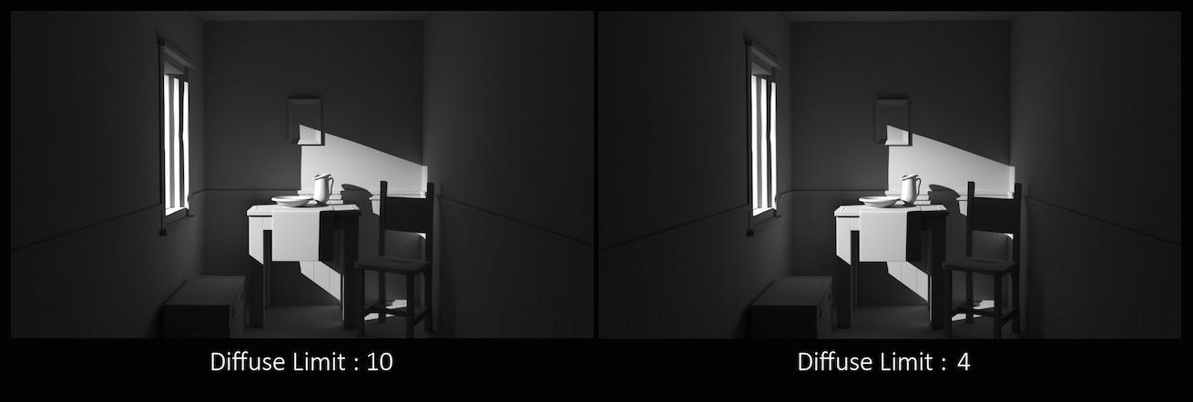
The number of times diffuse rays can propagate through your scene.
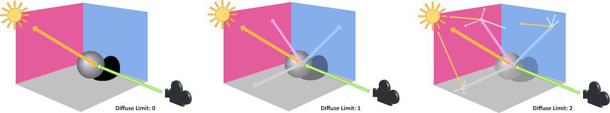
Unlike Reflect Limit and Refract Limit, this parameter will increase the overall amount of light in your scene and contribute to the majority of global illumination. With this parameter set to values greater than 0, diffuse surfaces will accumulate light from other objects in addition to direct light sources.
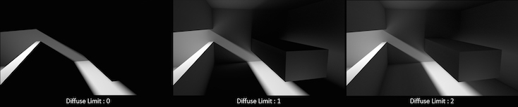
In this example, increasing the Diffuse Limit has a dramatic effect on the appearance of the final image. To replicate realistic lighting conditions, it is often necessary to increase the Diffuse Limit. However, since the amount of light contribution usually decreases with each diffuse bounce, increasing the Diffuse Limit beyond 4 hardly improve the visual fidelity of a scene. Additionally, increasing the Diffuse Limit can dramatically increase noise levels and render times.
This is a float because all limits are stochastically picked per-sample, so for example you can set the diffuse limit to 3.25 and have 25% of the rays with a diffuse limit of 4 and 75% of rays with a diffuse limit of 3.
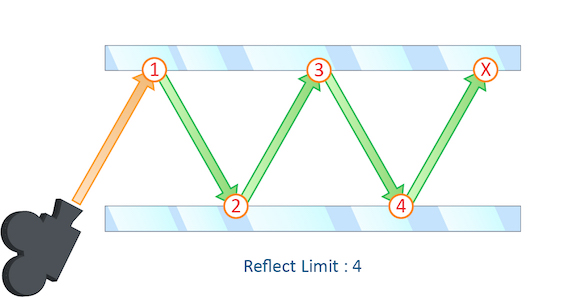
The number of times a ray can be reflected in your scene.
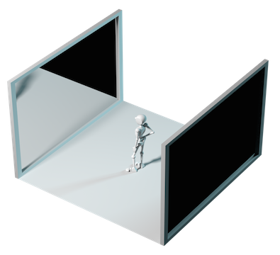
This example shows a classic “Hall of Mirrors” scenario with the subject placed between two mirrors.
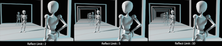
This effectively creates an infinite series of reflections.
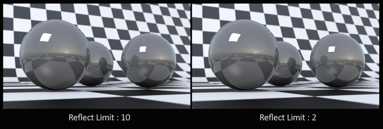
From this camera angle the reflection limits are very obvious and have a large impact on the accuracy of the final image. However, in most cases the reflection limit will be more subtle, allowing you to reduce the number of reflections in your scene and optimize the time it takes to render them.
Remember that the first time a light source is reflected in an object, it is considered a direct reflection. Therefore, even with Reflect Limit set to 0, you will still see specular reflections of light sources.
This is a float because all limits are stochastically picked per-sample, so for example you can set the diffuse limit to 3.25 and have 25% of the rays with a diffuse limit of 4 and 75% of rays with a diffuse limit of 3.
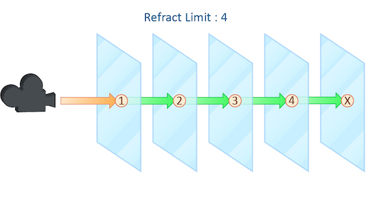
This parameter control the number of times a ray be refracted in your scene.
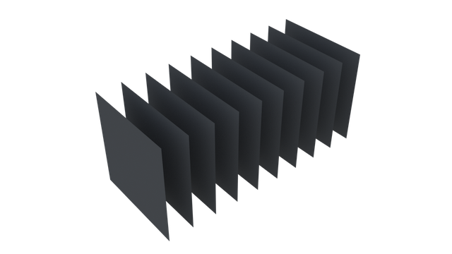
This example shows a simple scene with ten grids all in a row.
By applying a refractive shader, we will be able see through the grids to an image of a sunset in the background.
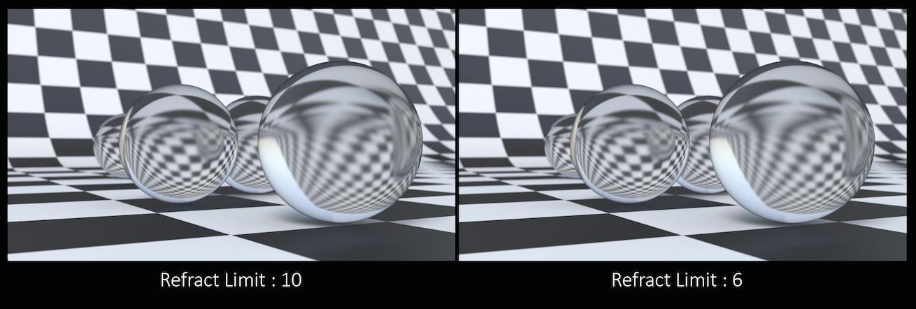
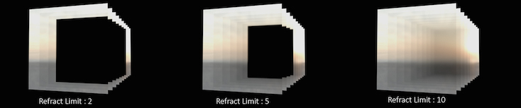
From this camera angle, in order for the image to be accurate, the refraction limit must match the number of grids that that are in the scene. However, most scenes will not have this number of refractive objects all in a row and so it is possible to reduce the refract limit without affecting the final image while also reducing the time it takes to render them.
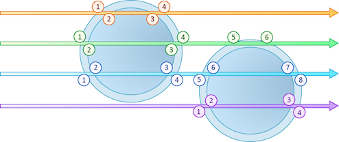
Keep in mind that this Refract Limit refers to the number of surfaces that the ray must travel through, not the number of objects.
Remember that the first time a light source is refracted through a surface, it is considered a direct refraction. Therefore, even with Refract Limit set to 0, you will see refraction of light sources. However, since most objects in your scene will have at least two surfaces between it and the light source, direct refraction is often not evident in your final render.
This is a float because all limits are stochastically picked per-sample, so for example you can set the diffuse limit to 3.25 and have 25% of the rays with a diffuse limit of 4 and 75% of rays with a diffuse limit of 3.
The number of times a volumetric ray can propagate through a scene. It functions in a similar fashion to the Diffuse Limit parameter.
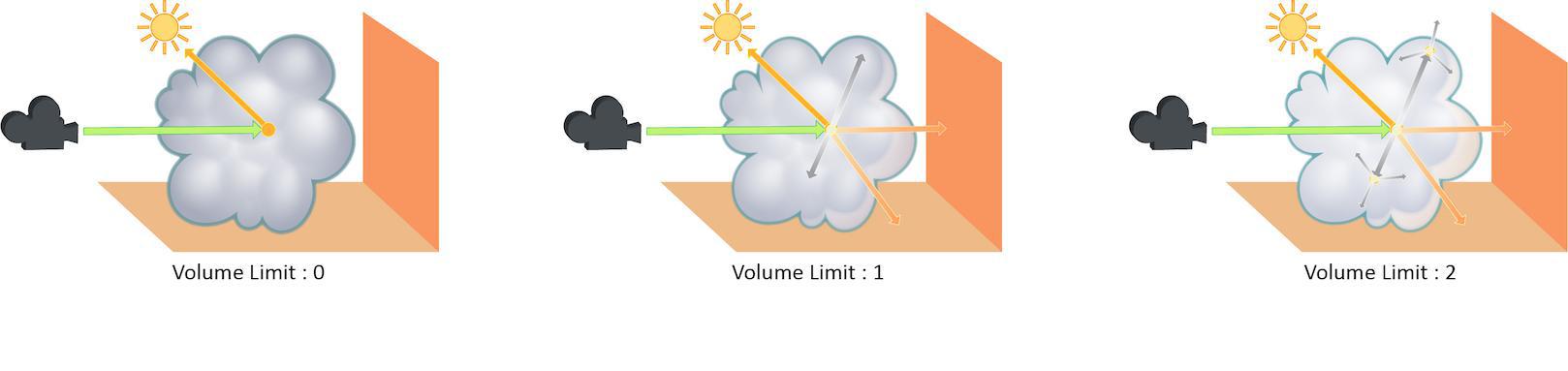
Increasing the Volume Limit parameter will result in much more realistic volumetric effects. This is especially noticeable in situations where only part of a volume is receiving direct lighting. Also, in order for a volumetric object to receive indirect light from other objects, the Volume Limit parameter must be set above 0.
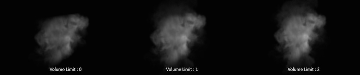
With the Volume Limit set to values greater than 0, the fog volume takes on the characteristic light scattering you would expect from light traveling through a volume. However, as with the Diffuse Limit, the light contribution generally decreases with each bounced ray and therefore using values above 4 does not necessarily result in a noticeably more realistic image.
Also, increasing the value of this parameter can dramatically increase the amount of time spent rendering volumetric images.
This is a float because all limits are stochastically picked per-sample, so for example you can set the diffuse limit to 3.25 and have 25% of the rays with a diffuse limit of 4 and 75% of rays with a diffuse limit of 3.
The number of times a SSS ray can propagate through a scene. It functions in a similar fashion to the Diffuse Limit parameter.
This is a float because all limits are stochastically picked per-sample, so for example you can set the diffuse limit to 3.25 and have 25% of the rays with a diffuse limit of 4 and 75% of rays with a diffuse limit of 3.
This parameter acts as a multiplier on Min Secondary Samples and Max Secondary Samples for indirect diffuse component.
This parameter acts as a multiplier on Min Secondary Samples and Max Secondary Samples for indirect reflect component.
This parameter acts as a multiplier on Min Secondary Samples and Max Secondary Samples for indirect refract component.
This parameter acts as a multiplier on Min Secondary Samples and Max Secondary Samples for indirect volume component.
This parameter acts as a multiplier on Min Secondary Samples and Max Secondary Samples for the SSS component.
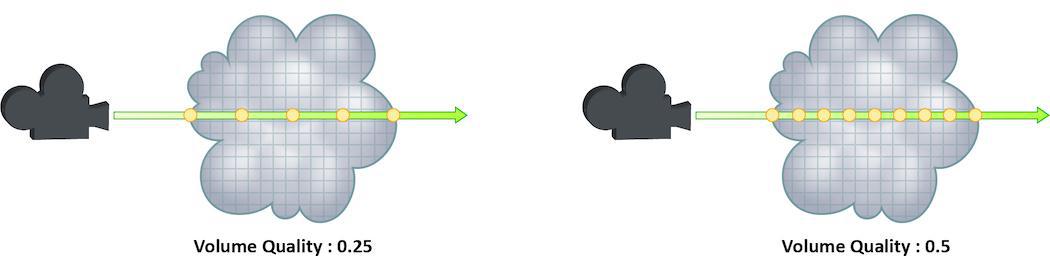
How finely or coarsely a volume is sampled as a ray travels through it. Volumetric objects are made up of 3-dimensional structures called Voxels, the value of this parameter represents the number of voxels a ray will travel through before performing another sample.
The default value is 0.25, which means that every one of every four
voxels will be sampled. A value of 1 means that all voxels are
sampled and a value of 2 means that all voxels are sampled twice. This
means that the volume step rate value behaves in a similar way to pixel
samples, acting as a multiplier on the total number of samples for
volumetric objects.
Keep in mind that increasing the volume step rate can dramatically increase
render times, so it should only be adjusted when necessary. Also, while
increasing the default from 0.25 can reduce volumetric noise, increasing
the value beyond 1 will rarely see similar results.
Whether to render this object as if it was a uniform-density volume. Using this property on surface geometry is more efficient than actually creating a volume object of uniform density, since the renderer can assume that the volume density is uniform and place samples more optimally. The surface normal of the surface is used to determine which side of the surface will render as a volume - the normal will point away from the interior. The surface doesn’t need be closed - if the surface is not closed, the volume will extend an infinite distance away from the surface. Non-closed surfaces may produce unexpected results near the edge of the surface, so try to keep the viewing camera away from the edges.
Determines how the samples are distributed when rendering a uniform volume
(karma:object:volumeuniform is enabled). This parameter must match the
density on the uniform volume shader in order to produce correct results.
The number of samples to generate when rendering a uniform volume
(karma:object:volumeuniform is enabled). The samples will be distributed
so as to produce an equal image contribution if they were all equal in
brightness.
Velocity multiplier used to reduce or exaggerate amount of motion blur on volumes.
Specifies the volume field by name that will be used for empty space culling. By default karma will use the 'density' field if it exists. If you are rendering an emissive volume in which some parts of the volume have zero density, but still need to be rendered, you should specify a different field using this parameter.
Some volume primitives can use a filter during evaluation of volume channels. This specifies the filter. The default box filter is fast to evaluate and produces sharp renders for most smooth fluid simulations. If your voxel data contains aliasing (stair stepping effects along edges), you may need to use a larger filter width or smoother filter to produce acceptable results. For aliased volume data, gauss is a good filter with a filter width of 1.5.
point
box
gauss
bartlett
blackman
catrom
hanning
mitchell
This specifies the filter width for the Volume Filter property. The filter width is specified in number of voxels. Larger filter widths take longer to render and produce blurrier renders, but may be necessary to combat aliasing in some kinds of voxel data.
When this is set to “Matte” mode, the object will be considered to be a
cutout matte. Any lighting contribution and alpha of the object will be
redirected to LPE AOVs with “holdouts” prefix. Holdout Mode does not affect
the utility AOVs such as ray:hitP and ray:hitN.
Background mode is similar to Matte. If it’s used for background
plates, it will appear “pre-lit” in indirect bounces, multiplied by shadow
contribution. Diffuse albedo of the shader is used to determine the pre-lit
irradiance.
When rendering point clouds, they can be rendered as camera oriented discs, spheres or discs oriented to the normal attribute.
When rendering curves, they can be rendered as ribbons oriented to face the camera, rounded tubes or ribbons oriented to the normal attribute attached to the points.
USD supports Curve Basis types that may not be supported directly in Houdini. In some cases, you may want to override the Houdini curve basis. For example, if you have linear curves in Houdini, you may want to render them with a Bezier, B-Spline or Catmull-Rom basis. This menu will force Karma to override the basis that’s tied to the USD primitives.
Note that the topology of the curves must match the target basis. For
example, when selecting any cubic curve basis, every curves must have at
least 4 vertices. For the Bezier basis, curves must have 4+3*N vertices.
Adjust shading position of shadow rays to avoid self-shadowing artifact on low-poly mesh due to discrepancy between smooth normals and face normals.
Custom label assigned to lights or objects for use with light path expression.
May be queried via objectstate vex function
and will be rightHanded or leftHanded depending on the geometry’s
winding order. This property is derived from USD geometry’s orientation
attribute and not directly settable.
For compound BSDFs with refractive components, only apply direct lighting for lights that belong in specified location. A light ray facing the same direction as geometry normal is considered “Outside”. For transparent material that are solid/closed-manifold, setting this parameter to “Outside” can improve render performance by reducing noise in direct lighting and cut down on wasted shadow rays.
Allows evaluation of glossy BSDF that’s seen by indirect diffuse bounce. This is a brute-force solution which may require significant number of diffuse rays to resolve, especially if Caustics Roughness Clamp parameter is set to very small value or Indirect Guiding feature is disabled.
Increasing this value can make caustics less noisy at the cost of accuracy.
Note
Roughness clamp only works with GGX BSDF and may not have any effect with Phong, cone, or specular BSDFs.
Noise threshold to determine the number of indirect rays cast for indirect bounce when the Convergence Mode is set to “Automatic”. Decreasing this threshold (for example, to 0.001) will theoretically send more indirect rays and decrease noise, however the “extra” rays will likely be cancelled out by the Max Ray Samples parameter. The correct way to decrease noise is to increase the number of samples per pixel, rather than change this threshold.
If you are using Variance Pixel Oracle, you should set the same value for both threshold parameters. Setting the oracle’s threshold lower may make the indirect component reach its threshold sooner and cast fewer indirect rays, but the oracle decides to cast more expensive camera rays because the amount of final noise in the beauty pass is higher than the oracle’s threshold.
When enabled, the object will turn into a “light portal” that only lets in certain portion of dome lights based on portal geometry visibility.
Defines this object as the low resolution object corresponding to said Texture Baking Object ID. This means that the texture space of this object is what is being baked. If no high resolution object exists for this Object ID, this is the rendered appearance for the texture in that space as well. This is required for texture baking.
Defines this object as the cage object corresponding to said Texture Baking Object ID. This means that this object is used to help resolve normal discontinuities during texture baking of the low resolution object. This is optional for texture baking.
Image plane pixel filters are used to combine multiple samples into a single pixel color. For example, the filter may choose a single sample (closest to the camera, or maximum value), or most commonly, the pixel filter will choose to average the sample values.
This parameter specifies a list of filters. These filters are specified as a JSON list.
Indicates whether to average multiple samples into the final color or whether to use the first ray that hits an object. This setting is deprecated in favor of image plane pixel filters.
When Karma quantizes pixels to 8 or 16 bit integer channels, this specifies the dithering to be used. This is only done if the AOV is specified as 8/16 bit output depth. It will not be done if conversion is done when writing floating point values to an image format that only supports 8/16 bit integer channel data.
Enable this to turn this image plane into Cryptomatte layer. See Cryptomatte for more info.
Maximum number of IDs that can be stored in a single pixel. A value of 6 is recommended.
Compression value between 0 and 10. Used to limit the number of samples
which are stored in a lossy compression mode for volume samples. The
compression parameter determines the maximum possible error in scalar
channels for each sample. For compression greater than 0, the following
relationship holds: Error = 1/(2^(10-compression))
These properties are used to specify default values for options normally
specified on the command line of the karma stand-alone renderer.
When rendering multiple frames (see frame_count), this specifies the
frame increment for each subsequent frame.
The render time limit is applied per image in a sequence rather than to the full render.