|
Houdini Engine for Unity
|
|
Houdini Engine for Unity
|
Houdini Engine for Unity supports generating Unity meshes as output geometry, as well as uploading Unity meshes to Houdini as input geometry.
By using Node Inputs or Object Path Input Parameter, Unity mesh geometry can be marshalled into Houdini. Assigned materials can be saved as primitive attributes with material paths, which will survive the roundtrip when exporting the same geometry back out to Unity.
The geometry output of a Houdini asset is usually a Unity Mesh, stored on a MeshFilter or MeshCollider.
An asset usually contains Objects, which in turn contain Geos, which contain Parts. This structure dictates how Unity meshes are generated.
Typically all geometry in a Part will be generated as a single mesh. Only collision groups or LOD groups can be used to split up the geometry into separate meshes. Other groups will be either combined into a single mesh, or if LOD groups are present, the those other geometry are ignored.
Note that, by default, meshes will be generated using split vertices (i.e. each triangle will have unique vertices). This can be changed to using Points (shared vertices) by enabling Generate Mesh Using Points checkbox in the ASSET OPTIONS section.
Level of Detail (LOD) meshes can be generated by using LOD Groups. Note that LOD is only supported for Unity 2017.1 and newer.
In Houdini, add the geometry for each LOD to a primitive group with a name starting with "lod". The alphabetical order of the group names will dictate the LOD order (i.e. lod0, lod1, lod2, etc).
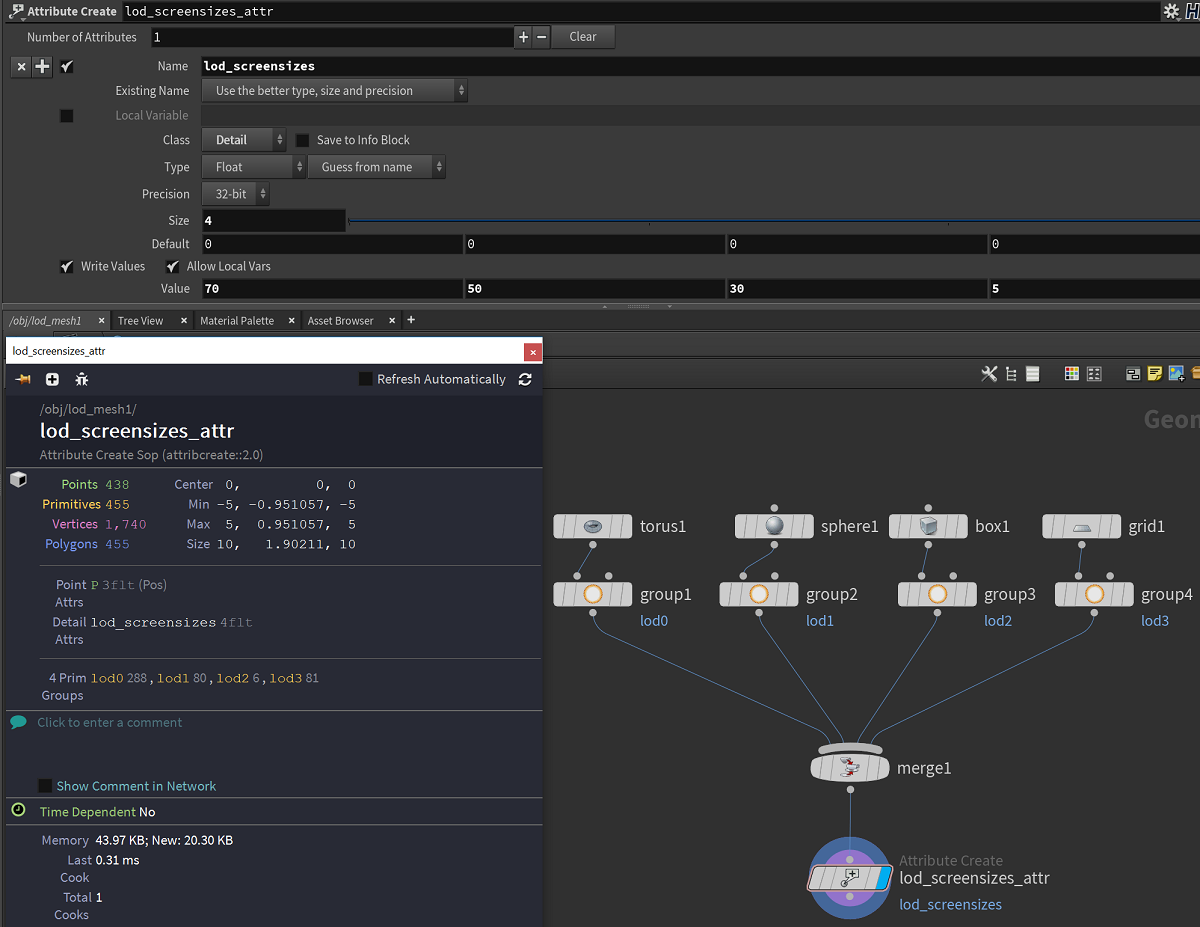
When the plug-in encounters these groups, a LODGroup component is added to the output GameObject, and child GameObjects are created containing the LOD meshes (one child for each LOD group). Make sure that the Use LOD Groups checkbox under the ASSET OPTIONS section is enabled (if not, enable then Recook the asset).
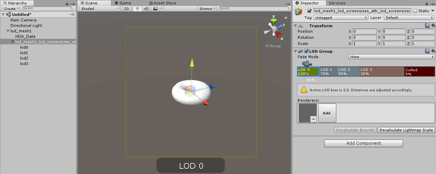
The screen relative transition height values used for the LODGroup can be specified by a detail float array attribute named "lod_screensizes". This float array should contain the corresponding number of float values, each of which should be in the range between 0 and 1, or between 1 to 100. For the later case, values over 1 will be divided by 100 in order to be compatible with Unity's LOD system. If this attribute is not specified, default values will be used where each LOD will receive an equal transition range between 0 and 1.
Note that packed geometry inside a LOD group will not be created as a LOD mesh. Rather it will be treated as instanced geometry (see Packed Primitives).
Colliders can be automatically added to generated meshes by using keywords in group names for geometry. These group names are:
Mesh Colliders:
Simple Colliders (Unity Primitive Colliders):
Convex:
Triggers:
Add trigger in the names above in order to convert the collider into a trigger (i.e. enable the Is Trigger toggle). Note that for Mesh Colliders, they must be convex.
The geometry with one of the above grouping will be generated as a separated mesh from other geometry, and set as the mesh in the MeshCollider component.
By default, the plugin always generates meshes with Triangle topology, even if the geometry Connectivity is set to Quadrilaterals. Instead, Quad topology meshes can be generated by doing the following:
Notes:
By default, the plugin will generate non-readable meshes. Yet readable meshes can be generated by specifying the integer attribute named unity_mesh_readable with a value of 1.
 1.8.6
1.8.6 
