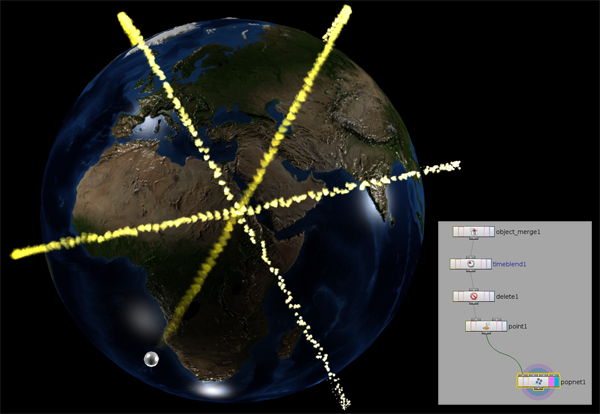
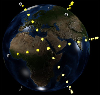
Hi, I have a earth and three small spheres are flying around it (orbiting). They are emitters for particles. These particles should feel like a sparkeling tail. Unfortunatly they are only born at precise frame time. But they should be born in the time between the frames, too. This way, they tail looks like a broken car exhaust ;-) How can I manipulate the source, so that a smooth tail appears? Example image here:
I am really thankfull for the input from this thread. With all that input I tried to do a video tutorial how to model a car from a blueprint. But unfortuantly that went not that well I assumed. And since I am doing this for a project of mine, I decided to set priority on my project.
But here are some hints for people who look for some information. First of all the way I integrate the blueprints to my process. This is taken from
Next some aid on car modelling by a blueprint. I did it nearly right the way that is described there
http//www.3dm3.com/tutorials/car3/
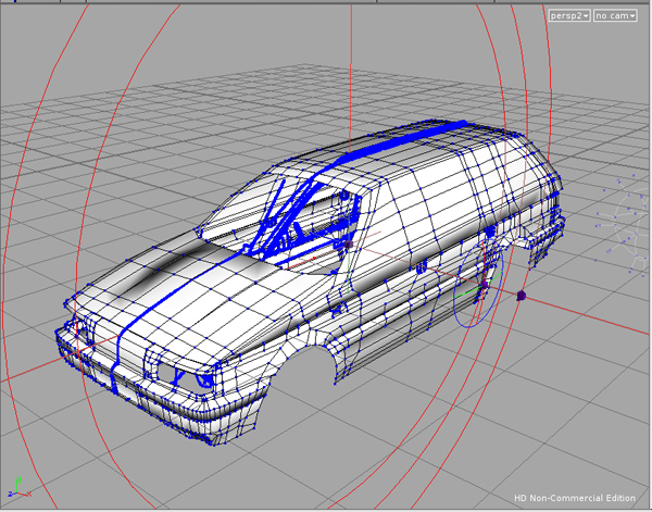
With this information I started modelling with a grid with 2x2 rows/colums. I extruded the edges and did it like in the tut mentioned above. Extruding and point editing where on my way. It is not really procedural, its more classic. But it works well in houdini. Sometimes you have to close holes in this process. How to is mentioned above in this thread. In the end houdine tries to create rounded shapes what you not always like on a car. But you can select all primitives that should have clean edgy shapes and use the edge cusp node to make them sharp in rendering. With that, it should be not a big problem to modell a car in the classic way in houdini. If I find the time after finishing my project in early summer, I maybe try to do a video tutorial again. Thanks, - Frankie
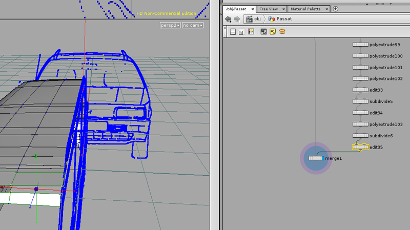
Thanks Greg! I will try this out in my next model. Because I got stuck at this point, I worked the hole morning with some subdivision, dissolving and point moving things, and now the door shapes are in the original body model. I am just at the point to blast out the windows … and then have a little work left in the lower parts ;-)
Unfortunatly I have to come back this early. This is where I am now:
As far I modelled from a short nonHoudini Tutorial. It says model this way, and when it comes to the doors, just cut them out. I liked that idea to avoid the polyknit problems mentioned above. And I thougt the knife tool could do the job. But now when I am here I found out that the knife tool can only cut one line. Thats not what I need. In Viewport right I would like to cut out the door with a shape (painted on the tablet) instead of a line. Is this somehow possible?
If not I will go into subdivisions and remodel the door stuff. In this particular case its not neccessary to open the doors.
BTW: I am satisfied with modelling a car in houdini ;-) This is the very first car i do, and it looks similar to the original one. Done just from photos. And its much faster than I was afraid of. Great ;-)))
Jeff, you don't have to be sorry. I have to be sorry not beeing precise enough in explaining my problem ;-) But you are a brilliant daysaver! Polyknit was the tool I was looking for! (Hard to find in the online help and the forum … I am shure that was told in the forum often enough … but the search word must be more precise/different). - Frankie
Thanks Jeff, but I dont feel that fuse is the right node for me (I tried it before, the same as with join, stitch and the other one). Instead of creating a new quad it is combining the selected quads. I am here:
I need a quad in the gap. I could extrude the lower geometry upwards to have a very small gap an then use fuse. But I am not sure if this is the right way. Is there no way to select three or four points and tell houdine to make a polygon out of them ? - Frankie
A stupid problem occured During extruding etc. two lines of extrusion are coming together again. Now there are two quads beside each other and between them is a gap. I want to select the four points, two from each quad, and want to tell houdini that this should be a polygon, so the gap is closed. I saw this once but I forgot where, and how to … Thanks, - Frankie
Thanks a lot for this answer. I played around with some of the parameters before … but now it was easier to be straight forward. First thing I did, was reducing the image size of the blueprints to a quarter. And you are right, the thick lines doubled the amount of points in the trace. I tried to make the lines thinner, but that had only medium success (it would be good if PS or the Trace Node could analyse line graphics to there skeleton minimum). With this I reduced the point amount around by the half to 48.000. The Filter build in Resample parameter brought it down again by around the half. The Facet node was able to reduce it more, but then there where to less points left. But I ended up with a point count reduced from 100.000 to around 5.000 ;-) Then I started my extrusions with a grid instead of a box. In fact it felt a lot faster to model. I am not sure if this speed has to to with the driver problems that are mentioned in another thread by a nvidia guy. I have a ati 4670 with the 9.10 driver in Windows 7 64 bit. I think it is allright now.
So now for the next time I will be in my cave and model the cars. And I watch the crumpling … masterclass some times more. And when I get stuck, I will come back to this thread again ;-) - Frankie
Hi there, I just started modelling two cars in Houdini. I will use this thread for occuring questions. Just from the beginning I have one special question and two general questions ;-)
General question I will try to model starting with a little box or grid. Finally I want to do some clothes simulation as in the Crumpling and Tearing Tutorial. If I start to model with a box my cars surface will have a thickness in the end. That seems allright for me. If I start with a grid, the car will only have a cover with no thickness. What kind of body should the car have to work best in a simulation like the mentioned above? Second general question would be In the mentioned tutorial the simulation is made with a low poly model and then transferred to the high poly model. Is it okay to model the car in detail and then work with a ‘poly reduce’d model in the simulation or should I stop in the modelling when it is rough, save it away for simulation and create the higher poly model from there in a new file?
The special question I run into the problem that this is the first time I do blueprint modelling in Houdini. I think thats not easy but i followed a tip in the odforce forum where somebody uses the trace node for three or for views that are used for the blueprint. Yesterday I tried it the first time, and I liked it a lot. But the system felt slow (Q9650, 8GB, Win64). So I started again today with the second car. I just imported one sideview (pixelimage with a linedraw abstract of the car, 9 pixel linewith, stored in rat format) with one trace node. Then I saw that it is made out of 100230 Points and edges. Much more accuracy than I need for a blueprint. I tried to play with the filter options, but it was not really satisfying because there was too much damage to the general geometry. Then I tried to add the resample node, but it was not much reduction to the amount of points. Poly reduced doesn't help, too. So its clear, I am doing something fundamentally wrong ;-)) Any hint to this current problem? - Frankie
Hi there, i have a problem, that occured before and I ignored it then, but since I have it again with a similar object I have to ask what the problem is, and how I can solve it.
I create a star. I take a platonic object, edit it to bring it in shape and then put 5 rotated copies of it in place (three nodes platonic->edit->copy).
No matter of what material I apply to it (in the picture it is plastic without specular), it renders as if the surface is smoothed out, so the upper hard edges are not going to display. Not to tell of the color break on the sides. It is simply wrong. It should look like a hard egded star but it doesn't.
What can I do to solve this? (I had the same problem with a ring, that was made out of a quadratic curve that was sweeped around a circle. In the editor, the ring had the hard edges I wanted, but rendered it looked like a donut)
hmm, i inserted a invert node after the alpha output from the texture. Notihing changes. If that would have been the problem (swapped black and white) the trees should have been transparent. so the error would be easy to locate … but everything is opaque. -/
Hi Alan, now it is in the morning in germany and I tried to get this thing working -) First of all, again thanks for the explanation. I forgot about creating input parameters (I saw that in the old school blog for vops, but forgot it). And I never knew, that it is possible to export a single value of the global varialbles … now i do.
Unfortunatly my VOP is is still rendering with a white area where it should be transparent. I have attached a screenshot of my wiring and parts of the shader view. When this vop is attached to my geometry in the scene, it is rendered the same as you see in the shader view. The white should be transparent. I have no input for the mapfile by now, because I want to let this work first for this unique setting. Instead I have the UV inputs to map the shader to UVs of the geometry. I hope this is not disturbing.
One error I could have made, could be the creation process of the Texture File. I can't remember that I made a photoshop file with a true alpha before. I always made gifs or similar where you just have to hide the background layer to have the transarency in the final file. So I gave that a new try in the morning. I took my photoshopfile, and added an explicit alpha channel where the tree area is finaly black, and the transparent area above is white. I saved this out as a tiff including alpha channels. Then I opened houdini and imported the file. When I select the different channels for viewing, everything seems okay. Viewing the alpha channel correctly displays the black and white mask. Then I selected save frame, and saved the image as random access file. C and A where not greyed out, and where pointing to C and A as I expected. Then I use this rat file as the input rgba in the texture node. Before yesterday I was not 100% sure if the texture file was okay, but now I am certenly sure for 99% ;-)
But unfortunatly, as you can see in the shader view, the alpha is still not blended out. If the alpha was swapped wrong, the trees would be transparent, but they are not. So if, I would simply invert. But I dont think that is the case. The OF Operator has nothing to play around with. KD is promoted outside, and set to 1 shows the complete image with no transparency, and set to zero makes the image complete invisible. Nothing to play around with, too. The key for the transparency is in the multipliers. But they seem to be correctly wired as I can see it in the book magic of houdini, and especially in your example. Any idea, what could have gone wrong? - Frankie
Hi Alan, thanks for this good example. I had no multiply in my vop. because i didn't know what i should use as the second input. I would like to test your setup. At the moment I dont know what your leftmost operator type is. And I dont know what your Kd and global_Of Operators are. Could you give me a hint ? And can you explain the diffuse export operator on the upper right? thanks and regards, Frankie
Unfortunatly I am running into the same problems by now. I did a lot of modelling an animation work by now, but now it comes to shading in my project. Actually I have a box, that should act as a faked wood billboard in the background of a scene. I created a tiff with the wood image, that should contain the alpha information. I converted this into a rat. Additionally I have a tiff that is black/white and could act as the alpha mask. I converted them to rats with import and save actions (this should be easier in coming versions … think of selecting tiffs and jpgs, and having a checkbox ‘autoconvert to rat’. According to the book ‘magic of houdini’ I created my own VOP/VEX that has the texture as the input for color, and the alpha.rat for the opacity AND alpha channel (vector to float .. output one). The shader ball shows a good result. In my scene the transparent areas of the image are white and not transparent. I really dont know how create my vop that will project an image uv-wise and has transparent parts for the billboard effect. Beside that, this shader is much to bright when I do a mantra testrun. Ambient was set to 0 (in the lightning operator). I don't really know how to create a good shader I need. - Frankie
Thanks a lot, at both! I didn't know, that the alpha was right there. I checked it with a tif export to afx, and now I am fine ;-) And I completley ignored the statistic tab in the Rop until now. The verbose setting did it, and was very interesting, too. Thanks a lot again! - Frankie
Thanks for your help Steven, and yes, you are right. Here is a light modified hipnc file that shows my problem.
If you open it, and jump into the PathBuilding Object (sorry some nodes inside are labeld german, but they are not interesting) you see a more or less big network. I am talking about the windows and the duplicate problem. In the network you find the interesting example duplicate nodes on the most left side. The window geometry with the original window is a bit above. The original window is placed as the upper left window on the front of the building. Now I triy to fill up all windows from that object.
When you open the example file, the problem duplicate nodes are bypassed. You see the most left duplicate 1 node (FirstRowThreeWin). That makes to duplicates into the right direction. This is okay. Next, the next window to the right is made with the duplicate 2 node. I cant make it with the first node, because it is a bit more forward than the other three windows. This window is okay. And last, I made upper left Window on the left side of the building with the duplicate 4 node. This one is rotated -90 degrees (and moved), because it is on the side. This one is okay.
The Problem nodes are the appended nodes as I described in my original posting. Click away the bypass flag on the duplicate 3 node. You see, that now there is on more window in the middle part of the building. If you looked very exactly to the building, you could have seen the problem. To make it better visible, click on the bypass node of the duplicate 1 node. Now you see, that from the left, there is a second window in the first row, that should not be there (because that was already created by duplicate node 1). What I wanted was, that the duplicate 3 node only takes the window, that was created by node 2, and make _one_ more duplicate to the right. But it made a transformed duplicate of the original, too. That was unwanted.
With the second example, this problem becomes more obvious. Click away the bypass flag on duplicate 5 node. These are the nodes for the windows on the left side of the building. When you clicked it away, you see that a second window appears on the left side, which is okay. But also the there is now an instance of the original window transformed outside the building! Same effect as with node 2 and three, but more obvious a problem.
The question is now, is it possible to append a duplicate node, to another duplicate node, that only duplicates the duplicate of the parent node, but not the original?
I hope this now more understandable (obviously not without looking at the file ;-)
Hi, I do a house geometry. The raw house is a box (mesh) with blasted holes for the windows. I did one window with curves/sweeps/skins. Then I distribute the windows with the duplicate function. Unfortunatly the holes are not complete symetric. As long as I do the duplicate in a symetric group, everything is allright. But when I have to start a new group, the original Window, where I append the duplicate sop, is allways in that group and then transformed as the duplicated instance. For my purposes I would like to append a duplicate sop to the original, and then would like to append more duplicate sops to that instance, but they should not contain the original window. … Procedurally thinking, I dont know how to avoid this, because the original is always in the chain of operators.
Hmm. Complicated to explain. e.g. you have the left upper window on the front of the house in a row as the original. With duplicate I can complete the complete row as long as the distance between the windows is the same. Now it goes to the right side of the house. I do another duplicate operation, rotate the window by 90 degrees and move it to the upper left position on the right side of the house. From that instance I would like to do a duplicate, that can fill up the complete upper row on the right side. But in this case, the unrotated, and unmoved original instance is inside the first duplicate, and will unneccessarily be duplicated and distributed the same way as the first rotated and moved duplicate. I would like to append a dup sop, that will only take the rotated and placed instance in account, but will ignore the original from where its coming.
How do you manage this problem? greeting, - Frankie
PS I am new to houdini and I do my first project. With the help of ‘magic of houdini’ and several video tutorials I solved a lot of problems until now. But some questions are left, where I cant find the answer at the moment.