| Since | 14.5 |
The goal of this shader is to produce physically plausible results while using intuitive rather than physical parameters. A large number of materials can be created with relatively few parameters. All parameters are in the zero to one range and represent plausible real-world values within that range.
Textures can be applied to all relevant parameters. Note that the texture value is always multiplied with the value of the parameter.
Note
This is a SHOP shader, which means it cannot be layered with other shaders.
If you need to do this, or if you need more control, you can use ![]() Principled Shader VOP which this shader is based on.
Principled Shader VOP which this shader is based on.
Parameters 
Surface 
Base Color
The overall color of the surface. Depending on other parameters, this can have different effects.
When Metallic is 0.0, Base Color controls the color of diffuse reflections. Use Reflect Tint to also tint reflections.
When Metallic is 1.0, diffuse is faded and Base Color only controls the color and intensity of reflections.
Use Sheen Tint to tint the Sheen effect with the Base Color.
Metallic
Values closer to 1 give the shader a more metallic appearance.
This is done by fading out the diffuse component and driving reflectivity by Base Color. This makes it easy to create the colored reflections typical of metallic materials.

Reflect
Controls the reflectivity of surfaces facing the viewer. This replaces the Index of Refraction parameter found on other shaders to allow for more direct control over visual appearance.
When a surface is rotated away from the viewer, more and more light is reflected regardless of this parameter’s value. At 90 degrees away from the viewer, 100% of the light is reflected, as in the real world.
Tip
How shiny an object appears mostly depends on it’s Roughness rather than it’s Reflect value. When you intend to vary shininess using a texture, Roughness is usually the better parameter to use.
Note
For additional artistic control, you can disable reflections completely by setting Reflect exactly to 0.0. When using a texture, this effect also occurs in completely black areas of the texture.

The effect of Reflect on a black object in a white environment. Note how reflections at the edges are not affected unless Reflect is exactly 0.0.

Note
The effect of this parameter diminishes with increasing Metallic values, since metallic reflectivity is tied to Base Color.
Reflect Tint
Tints reflections with the Base Color. This is not typical of non-metallic materials, but can be used for artistic purposes.

Note
The effect of this parameter diminishes with increasing Metallic values, since metallic reflections are always tinted by Base Color.
Roughness
Controls how dull a surface appears. A value of 0.0 results in a smooth surface with perfectly sharp reflections. A value of 1.0 produces a completely dull surface. Under the hood, this simulates microscopic bumps which become more pronounced the higher the Roughness, causing reflected light to be scattered more.
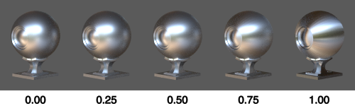
The effect of Roughness on a material with Metallic set to 1.0:

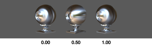
The effect of Roughness on a material with Metallic set to 0.0:

Anisotropy
Causes reflections to be stretched in the direction defined by Anisotropy Direction.
This simulates microscopic bumps with a directional bias, causing light to be scattered more in the defined direction. This is typical of brushed metals.

The effect of this parameter increases with Roughness. It has no effect at all when Roughness is 0.0.
Anisotropy Direction
Controls the direction of Anisotropy relative to the UV coordinates of the surface. At 0.0, reflections are stretched in the U direction. At 0.5, the direction is rotated by 90 degrees to the V direction. 1.0 equals 180 degrees. Since the effect is symmetrical this produces the same result as 0.0.
The direction of rotation also depends on the UV layout. When the UVs are layed out such that textures appear on the surface without mirroring, higher values rotate counter-clockwise.
The effect of this parameter diminishes with decreasing Roughness and Anisotropy.
This parameter has it’s own Filter Type parameter which appears when Use Texture is enabled. This defaults to Point (No Filter), which usually works best. When you change this to an actual filter like Gaussian, artifacts may appear around the transition between areas with different direction values.
Tip
The 0-1 range makes it easy to apply a texture to this value. To find the texture value needed for a certain direction:
-
Turn off Use Texture under Anisotropy Direction.
-
Try out values on the slider and kick off test renders until you get the desired result.
-
Paint the slider value into your texture.
-
Turn Use Texture back on.
To help with this workflow, the Anisotropy Direction remembers it’s value whenever Use Texture is toggled. It defaults to 1.0 when Use Texture is enabled, meaning you get the unmodified texture data.
Subsurface
Gives the appearance of subsurface scattering. This is a fast approximation and doesn’t perform actual SSS.

Note
The effect of this parameter diminishes with increasing Metallic values.
Sheen
Produces extra reflections at grazing angles, which can be useful to match certain cloths and some other materials.

Note
The effect of this parameter diminishes with increasing Metallic values.
Sheen Tint
Tints reflections produces by Sheen with the Base Color. This can help with matching certain cloth materials.

Note
The effect of this parameter diminishes with increasing Metallic values.
Coat
Controls the intensity of coat reflections. The coat can have a different Roughness value than the base layer, see Coat Roughness.

Coat Roughness
Controls the roughness of Coat reflections.

Filter
The type of texture filter to use. This is used for all Surface parameters except for Anisotropy Direction, which has it’s own Filter parameter.
Filter Width
The width of the filter to use when sampling textures. Higher values causes the texture to be filtered/burred more.
Emission 
Emission Illuminates Objects
Controls whether emission should illuminate other objects.
Emission Color
The color of light emitted from the surface.
Emission Intensity
Intensity of light emitted from the surface.
Bump & Normals 
Base 
Texture Type
Bump
A bump map creates the appearance of surface detail without actually modifying the geometry or changing the object’s silhouette.
Depending on the Channel parameter the R, G, B channel or the luminance is used as the bump height.
Normal
Set the normals from an RGB texture. After reading the texture values, they are modified according to the Normal Space, Flip X and Flip Y parameters and transformed to the space defined by the Vector Space.
Texture Color Space
The texture’s color space.
Vector Space
The space in which the vector-based operations Normal and Vector Displacement are applied.
UV Tangent Space
Use the space defined by the Surface Normal and the UV-tangents. Using this space allows normal textures to be applied to deforming objects, since the vector applied relative to the surface’s orientation, rather than simply in object space.
Object Space
Use the object’s transform.
Offset
This offset is added to the value before Effect Scale is applied.
Effect Scale
The effect of the operation is scaled by this value.
In Normal mode, this scales the rotation of normals away form the input normal.
Texture Path
The image file to use as a texture map.
UDIM Filename Expansion
UDIM texture filename expansion.
The UDIM coordinate is computed based on the uv-coordinate: 1000 + int(u)+1 + int(v)*10.
Example: “map_<UDIM>.rat” returns “map_1044.rat” with u=3.1, v=4.15
Wrap
Determines how the image is evaluated when the texture coordinates are outside the range 0-1. The options are:
Repeat
(string value repeat). The image map repeats outside the
range 0 to 1. Basically, the integer component of the texture
coordinate is ignored.
Streak
(string value streak). Texture coordinates are clamped to
the 0 to 1 range.
Decal
(string value decal). Coordinates outside the range 0 to 1
will evaluate to the border color rather than an image
color.
Filter
Type of anti-aliasing filter to be used for evaluation. The options are:
Box
(string value box)
Gaussian
(string value gauss)
Bartlett/Triangular
(string value bartlett)
Sinc Sharpening
(string value sinc)
Hanning
(string value hanning)
Blackman
(string value blackman)
Catmull-Rom
(string value catrom)
Mitchell
(string value mitchell)
Point Sampling
(string value point)
Filter Width
Blur the texture based on derivatives in shading contexts. For contexts that do not provide derivatives (such as the sop context), this parameter will have no effect and you should use Texture Blur or Pixel Blur instead. In shading contexts, filtering will be proportional to the micropolygon size with a filter width of 1, filtering one micropolygon.
Channel
The component to use with the scalar operations Bump and Displace Along Normal.
Image Plane
The image plane to read from the texture.
Tip
Tangent-space normals exported using the Shading Tangent-Space Normal parameter on the ![]()
![]() Mantra ROP are exported to the
Mantra ROP are exported to the Nt image plane by convention.
Normal Space
In Normal mode, controls in what format the input is stored.
0 to 1
The components of the normal are in the 0-1 range. This is typically done in textures in order to store values in the positive and visible range.
-1 to 1
The components of the normal are in their natural, normalized state.
Flip X
Flip the input normals in X, before applying the Vector Space.
Flip Y
Flip the input normals in Y, before applying the Vector Space.
Coat 
Separate Coat Normals
When enabled, grants separate control over the Coat reflection layer’s normals. For example, this allows you to create a scratched coat layer with a smooth base layer underneath.
The rest of the parameters on this tab are the same as on the Base tab above.
Displacement 
Displacement Bound
The maximum bounds that the displacement shader will move geometry. This is defined in “camera” space. The absolute value is used to determine the bounds.
True Displacement
Whether to do “real” displacement (actually modify geometry at render time, allowing the silhouette of the object to change). If you turn this option off, the values of the displacement tab will be used as a bump map (creating the appearance of depth but not actually modifying the geometry or changing the object’s silhouette).
Include In Exported Tangent Normals
Controls whether displacement should affect the normals exported through the Nt variable.
Tip
To export the tangent-space normals generated by the shader as an image plane, enable the Shading Tangent-Space Normals (Nt) parameter on the ![]()
![]() Mantra ROP's Images/Extra Image Planes tab.
Mantra ROP's Images/Extra Image Planes tab.
Texture Type
Displace Along Normal
Moves the surface in the direction of it’s normal.
Depending on the Channel parameter the R, G, B channel or the luminance is used as the height.
Vector Displacement
Moves the surface by the texture value. The value is applied in the chosen Vector Space.
Texture Color Space
The texture’s color space.
Vector Space
The space in which the vector-based operations Normal and Vector Displacement are applied.
UV Tangent Space
Use the space defined by the Surface Normal and the UV-tangents. Using this space allows normal textures to be applied to deforming objects, since the vector applied relative to the surface’s orientation, rather than simply in object space.
Object Space
Use the object’s transform.
Offset
This offset is added to the value before Effect Scale is applied.
Effect Scale
The effect of the operation is scaled by this value.
In Normal mode, this scales the rotation of normals away form the input normal.
Texture Path
The image file to use as a texture map.
UDIM Filename Expansion
UDIM texture filename expansion.
The UDIM coordinate is computed based on the uv-coordinate: 1000 + int(u)+1 + int(v)*10.
Example: “map_<UDIM>.rat” returns “map_1044.rat” with u=3.1, v=4.15
Wrap
Determines how the image is evaluated when the texture coordinates are outside the range 0-1. The options are:
Repeat
(string value repeat). The image map repeats outside the
range 0 to 1. Basically, the integer component of the texture
coordinate is ignored.
Streak
(string value streak). Texture coordinates are clamped to
the 0 to 1 range.
Decal
(string value decal). Coordinates outside the range 0 to 1
will evaluate to the border color rather than an image
color.
Filter
Type of anti-aliasing filter to be used for evaluation. The options are:
Box
(string value box)
Gaussian
(string value gauss)
Bartlett/Triangular
(string value bartlett)
Sinc Sharpening
(string value sinc)
Hanning
(string value hanning)
Blackman
(string value blackman)
Catmull-Rom
(string value catrom)
Mitchell
(string value mitchell)
Point Sampling
(string value point)
Filter Width
Blur the texture based on derivatives in shading contexts. For contexts that do not provide derivatives (such as the sop context), this parameter will have no effect and you should use Texture Blur or Pixel Blur instead. In shading contexts, filtering will be proportional to the micropolygon size with a filter width of 1, filtering one micropolygon.
Channel
The component to use with the scalar operations Bump and Displace Along Normal.
Image Plane
The image plane to read from the texture.
Tip
Tangent-space normals exported using the Shading Tangent-Space Normal parameter on the ![]()
![]() Mantra ROP are exported to the
Mantra ROP are exported to the Nt image plane by convention.
Settings 
Component Labels 
Diffuse
Specifies a label for the diffuse component. This can be used to export contributions from this component to a separate image plane.
Base Reflection
Specifies a label for the base reflection component. This can be used to export contributions from this component to a separate image plane.
Coat Reflection
Specifies a label for the coat reflection component. This can be used to export contributions from this component to a separate image plane.
Misc 
UDIM Filename Expansion
UDIM texture filename expansion.
The UDIM coordinate is computed based on the uv-coordinate: 1000 + int(u)+1 + int(v)*10.
Example: “map_<UDIM>.rat” returns “map_1044.rat” with u=3.1, v=4.15
| See also |