| On this page |
Overview 
The mantra output driver node uses mantra (Houdini’s built-in renderer) to render your scene. You can create a new mantra node by choosing Render ▸ Create render node ▸ Mantra from the main menus. You can edit an existing render node with Render ▸ Edit render node ▸ ‹node name›. To see the actual network of render driver nodes, click the path at the top of a network editor pane and choose Other networks ▸ out.
You can add and remove properties from the output driver just like you can for objects. If you add object properties to the render driver, they define defaults for all objects in the scene. Select a render node, and in the parameter editor click the ![]() Gear menu and choose Edit rendering parameters to edit the properties on the node. For more information on properties, see properties. For more information on adding properties to a node see the Edit Parameter Interface.
Gear menu and choose Edit rendering parameters to edit the properties on the node. For more information on properties, see properties. For more information on adding properties to a node see the Edit Parameter Interface.
For complex scenes involving multiple render passes, separate lighting and shadow passes, and so on, you can set up dependency relationships between render drivers by connecting driver nodes together. See render dependencies.
User guide 
Mantra Attributes 
The following attributes on geometry control how mantra renders the geometry.
orient
Orientation of curve/point primitives. Curves and points will be oriented so that their normals point in the direction of the orient vector attribute.
v
(velocity) Used for velocity motion blur computations.
uv
Default attribute for the -u command-line option.
vm_photon, vm_surface, vm_displace, shop_vm_photon
shop_vm_surface, shop_vm_displace
Shader overrides (per primitive).
width, pscale
Controls width of curve/point primitives (see below).
scale
Not used by mantra.
Note
When mantra decides the size of point primitives, it looks for the following attributes in order:
-
Point attribute
width -
Point attribute
pscale -
Detail attribute
width -
Detail attribute
pscale
To decide the width of curve primitives, mantra looks for the following attributes in order:
-
Vertex attribute
width -
Point attribute
width -
Primitive attribute
width -
Detail attribute
width -
Point attribute
pscale
The first attribute mantra finds controls the size/width of the point/curve.
Parameters 
Render to File
Renders with the last render control settings, using the path specified in Output Picture.
Render to MPlay
Renders with the last render control settings, redirecting rendered frames to MPlay, instead of the specified path. NOTE
If enabled, deep images and cryptomatte images will still be written out to their specified output path.
Render Control
Opens the render control dialog to allow adjustments of the render parameters before rendering.
Valid Frame Range
Controls whether this render node outputs the current frame (Render any frame) or the image sequence specified in the Start/End/Inc parameters (Render Frame Range).
Render Frame Range (strict) will render frames START to END when it is rendered, but will not allow frames outside this range to be rendered at all. Render Frame Range will allow outside frames to be rendered. This is used in conjunction with render dependencies. It also affects the behavior of the 'Override Frame Range' in the Render Control dialog.
Two possible cases where you'd want the strict behavior:
-
A 60 frame walk cycle written out to a geo, but part of a larger ROP net to render out a larger frame range.
-
A texture loop from 1-20.
Otherwise, you will usually set this to non-strict.
Render Current Frame
Renders a single frame, based on the value in the playbar or the frame that is requested by a connected output render node.
Render Frame Range
Renders a sequence of frames. If an output render node is connected, this range is generally ignored in favor of frames requested by the output render node.
Render Frame Range (Strict)
Renders a sequence of frames. If an output render node is connected, this range restricts its requested frames to this frame range.
Start/End/Inc
Specifies the range of frames to render (start frame, end frame, and increment). All values may be floating point values. The range is inclusive.
These parameters determine the values of the local variables for the output driver.
For example, if the parameters are set to:
Start |
End |
Inc |
|---|---|---|
10.5 |
12 |
0.5 | |
…there will be 4 frames rendered (10.5, 11, 11.5, and 12), so $NRENDER will have a value of 4. $N will have the following values at each frame:
Frame |
|
|---|---|
10.5 |
1 |
11 |
2 |
11.5 |
3 |
12 |
4 |
Render With Take
The output driver will switch to this take before rendering and then restore the current take when rendering is done.
Tip
use chs("take") to use this value in other parameters. See the chs expression function for more information.
Camera
The path the to camera object to use to render the scene, for example /obj/cam1.
Override camera resolution
Normally the image resolution is set on the camera object. Turn this on to enable controls that modify or override the camera’s settings.
Resolution scale
When Override camera resolution is on, allows you to scale whatever resolution is set on the camera. To completely override the camera’s resolution, choose “User specified resolution”.
Resolution override
When Override camera resolution is on and Resolution scale is “User specified resolution”, lets you set the resolution of the output image, overriding the settings on the camera.
Pixel Aspect Ratio
The pixel aspect ratio represents the width of a pixel divided by the height of a pixel. It is not the aspect ratio of the image (which is determined by the resolution of the image). This parameter does not affect rendering, it is only used to change how images are displayed, by stretching the pixels by this factor.
Images 
Output picture
The image or device where the resulting image will be rendered. You can set this value to ip which renders the image in MPlay, or you can save it to an image. The following image types are supported: .pic, .tif, .sgi, .pic.gz, .rat, .jpg, .cin, .rta, .bmp, .tga, .rad, .exr, and .png.
Include $F in the file name to insert the frame number. This is necessary when rendering animation. See expressions in file names for more information.
Output device
The image format or device for the output image. If you leave this at the default value of Infer from filename, the image format will be selected based on the file extension (eg. .pic will automatically generate a Houdini format image.)
Create Intermediate Directories
When turned on, creates intermediate parent directories for output files as needed. Currently only applies to generated scripts, images, and shadow maps.
Skip Existing Frames
Skip rendering of existing frames. There are three values for this parameter.
Overwrite existing frames
This option will render every frame, regardless whether there’s a file on disk or not.
Skip frames that exist
If there’s a disk file that matches the vm_picture parameter, no
render will be performed.
Skip frames that are valid images
If a disk file exists, the integrity of the image is checked before rendering is performed. This option incurs the cost of reading the image, but will re-render images that weren’t fully rendered.
Output 
Pixel filter
Specifies the pixel filter used to combine sub-pixel samples to generate the value for the single pixel. The filter is normally specified as a filter type (eg. gauss) followed by an x and y filter width in pixels. To blur the image, increase the filter width.
There are several different pixel filters available.
minmax ‹style›
The style may be one of:
-
min– Choose the value of the sample with the smallest z value (closest to camera). -
max– Choose the value of the sample with the maximum z value (farthest from camera). -
median– Choose the value of the sample that has the median z value of all samples. -
edge– Filter using a unit box but only averages samples with object coverage. This filter will have the effect of disabling external edge antialiasing. -
ocover– First, choose the object which covers most of the pixel, then take the average value from the sub-pixels of that object only. This filter is similar toedgebut it also disables internal edge antialiasing between object boundaries. -
idcover– First, choose the object which covers most of the pixel, then select a single sample from that object for the pixel value. This filter is similar toocoverbut it will not average any samples. Use this filter mode for planes that will be interpreted as integers, such as object or primitive identifiers. The sample chosen will be unordered. -
omin– First, choose the object which covers most of the pixel, then choose a single sample from that object for the pixel value. Chooses the sample with the smallest z value (closest to camera). -
omax– First, choose the object which covers most of the pixel, then choose a single sample from that object for the pixel value. Chooses the sample with the maximum z value (farthest). -
omedian– First, choose the object which covers most of the pixel, then choose a single sample from that object for the pixel value. Chooses the sample with the median z value.
point
Choose the sub-pixel closest to the center of the pixel.
box [‹width› ‹height›]
Use a box filter to combine the sub-pixels with a filter size given by width/height.
gaussian [‹width› ‹height›]
Use a Gaussian filter to combine the sub-pixels with a filter size given by width/height.
bartlett [‹width› ‹height›]
Use a Bartlett (cone) filter to combine the sub-pixels with a size width given by width/height.
blackman [‹width› ‹height›]
Use a Blackman filter to combine the sub-pixels with a filter size given by width/height.
catrom [‹width› ‹height›]
Use a Catmull-Rom filter to combine the sub-pixels with a size width given by width/height.
hanning [‹width› ‹height›]
Use a Hanning filter to combine the sub-pixels with a filter size given by width/height.
mitchell [‹width› ‹height›]
Use a Mitchell filter to combine the sub-pixels with a filter size given by width/height.
sinc [‹width› ‹height›]
Use a sinc filter to combine the sub-pixels with a filter size given by width/height.
edgedetect
Use an edge detection filter to find edges based on z-depth, object boundaries, and color gradients.
combine -t ‹tolerance›
Use a Ray Histogram Fusion-based filter to combine the sub-pixels with the given similarity tolerance.
Note
This option is very slow and may eliminate some noise in an image, even if the noise is supposed to be there (ie, not just noise due to undersampling), resulting in loss of detail.
denoise optix [-a ‹AOV›]
Sample filter
Controls how transparent samples are combined to produce the color values for individual pixel samples. The sample filter is used to composite transparent surfaces before the pixel filter produces final pixel colors.
Opacity Filtering (alpha)
Uses the opacity (Of) values for transparent samples for compositing. This option should be used whenever correct transparent compositing is required. For example, when rendering volumes, sprites, or transparency.
Full Opacity Filtering (fullopacity):
When stochastic transparency is enabled, this option causes a channel to be evaluated and composited with every opacity evaluation - as opposed to only being composited with the samples that are selected for full shading. It can be used to produce smoother results for channels that are fast to evaluate such as Ce or direct_emission. When stochastic transparency is disabled, this option behaves the same way as Opacity Filtering.
Closest Surface (closest)
Ignores the opacity values and just copies the color for the closest transparent sample into the image. This option disables transparency for a given deep raster plane and will only produce the closest sample results.
Quantization
The storage type for the main image. The type of quantization used will affect image quality and size. If you need to adjust the image’s dynamic range in compositing, you should normally leave this value at the default of 16-bit floating point.
The default is "float16" for the first plane, and "float" for secondary planes. You can override the first plane’s value with the -b command line argument to mantra.
Gamma
Sub-pixel output
Normally, sub-pixel samples are filtered using the pixel filter defined on an image plane. When this is turned on, each sub-pixel is output without any pixel filtering performed.
The image:resolution property will be scaled by the image:samples property to determine the actual output image resolution. For example, if image:resolution was (1024,512) and image:samples was (4,6), the image rendered would have a resolution of 4096 by 3072. Each pixel would represent a single unfiltered sub-pixel sample.
Tiled render
When you render a target node with this option on using HQueue, the server will split frames to render into separate tiles and render each tile as a separate job. When you render locally with this option on, Mantra will render a single tile instead of the entire frame.
Tiled render can also be enabled using -t command line option to mantra, which can be used to render a tile locally without having to generate an IFD for each tile with Tiled render enabled.
Horizontal tiles
Split the frame into this number of tiles horizontally, when Tile render is on.
Vertical tiles
Split the frame into this number of tiles vertically, when Tile render is on.
Tile index
Which tile to render, when rendering locally with Tile render on. Tile numbers start at 0 in the top left and increase left to right, top to bottom.
Create image from viewing camera
Renders an image from the viewing camera. Sometimes, it is useful to skip this render, for example, when rendering shadow maps.
Auto-generate shadow maps
Enable or disable shadow map generation. Each light also has its own controls to determine whether shadow maps will be generated.
Auto-generate environment maps
Enable or disable environment map generation. Each object can be set up to generate an environment map of all the other objects in the scene.
Auto-generate photon maps
Enable or disable photon map generation.
Extra image planes 
Export components
A whitespace-separated list of shading component names that will be computed for export. If you have defined new component labels in your materials, these can be added to the list so that they are exported for per-component export planes. If you are not using some components, remove them from the list to improve render efficiency.
PBR light exports assume that this list is complete - that is, all components created by shaders are listed. If there are unlisted components, light exports may be missing illumination from these components.
Shading position (P)
Shading depth (Pz)
Shading normal (N)
Combined lighting (per-component)
Add an extra image plane for the combined lighting (all components) using pre-defined settings. For finer control, add the image channel using the generic image plane interface.
Direct lighting (per-component)
Indirect lighting (per-component)
Combined emission
Direct unshadowed
Direct ray samples
Indirect ray samples
SSS single/multi
Surface Unlit Base Color (basecolor)
Surface Unlit Diffuse Color (diffcolor)
Surface Unlit Specular Color (speccolor)
Surface Emission Color (emitcolor)
Surface SSS color (ssscolor)
Surface Metallic (metallic)
Surface Roughness (specrough)
Extra image planes
These controls let you output VEX variables as auxiliary image planes, either as extra planes in the output file or extra files.
Tip
As of Houdini 9.1, each channel can now be written out to a different file. This lets you work with OpenEXR programs that don’t support multiple channels in a single .exr image.
You can also do fancy stuff like send one channel to the md device (a non-interactive MPlay window), or split your image into multiple .pic files with a handful of .tif files thrown in. But if the primary image is ip, all planes go to ip.
The Channel Name parameter lets you give the channel in the output file a different name than the default (the name of the VEX variable). For example, you want to send out the Of variable. If the Channel Name is left blank, the plane name in the .pic file will be Of. If you set Channel Name to Opacity, the plane in the .pic file will be called Opacity.
Deep output 
Deep Resolver
When generating an image, mantra runs the sample filter to composite samples to a single color. Mantra then runs the pixel filter to produce the final color for a pixel. A deep resolver is used to store information about each sample prior to sample filtering. This allows the image resolver to store information about each individual sample before compositing.
If you want to change the vm_deepresolver through Python, you have to specify one of the three tokens to represent the available modes: null, shadow, camera.
No Deep Resolver
Deep image will not be output.
Deep Shadow Map
Only the opacity (Of) and depth (Pz) image planes will be written out.
Deep Camera Map
All planes selected for deep images will be written out. Use Exclude from DCM to leave a specific image plane from the deep image output.
DCM Filename
The file to generate when the Deep Camera Map resolver is used.
DCM Pre-Composite Samples
The samples stored in the deep file can be stored as either uncomposited, meaning that each sample is independent of any other sample for the same pixel; or it can be stored pre-composited, meaning that each sample stores the accumulated opacity of the sample behind it and the opacity of the sample itself.
Force DCM Pixel Filter on Image Planes
When rendering DCM, force regular/non-deep image planes to have the same pixel filtering as DCM’s (i.e. Unit Box filter).
Meta data 
Artist
The name of the image creator. By default uses the current user’s log in name.
Houdini, TIFF, PNG formats
Comment
A text comment to include in the output file.
Houdini, OpenEXR, PNG formats
Hostname
The name of the computer where this image was created.
MPlay tile order
The direction in which MPlay renders the image. Possible values are "middle" (middle out), "top" (top down), or "bottom" (bottom up).
MPlay session label
When rendering to MPlay, all Houdini sessions will send the output to the same MPlay flipbook. This can be problematic when running multiple Houdini sessions. The MPlay Label lets you specify a label for the MPlay associated with the output driver. Only renders which match the given label will be sent to that MPlay.
Houdini Process ID
Uses the operating system process identifier so that the MPlay flipbook will only accept renders from that Houdini session.
HIP Name
Uses the $HIPNAME variable so the MPlay will only accept renders from the running $HIP file.
Output Driver Name
The MPlay flipbook will only accept renders from the given output driver. For example, if you copy paste the output driver, each output driver will be sent to different MPlay flipbooks because the operators will have different names.
If there are multiple Houdini sessions, there may be output drivers in the other session which match the same operator name.
For example, say you have two output drivers: “High quality” and “Low Quality”. If you set the MPlay Label to different values for the two output drivers, each render will be sent to different MPlay sessions.
MPlay gamma
Display gamma for MPlay, from 0.0 to 4.0.
JPEG quality
JPEG Quality, integer from 10 to 100.
TIFF compression
Type of image compression to use in TIFF files. Possible values are "None", "LZW", "AdobeDeflate", "Deflate", "PackBits", "JPEG", "PixarLog", "SGILog", "SGILog24", "LZMA", "Zstd".
EXR Compression
Compression type for EXR format images. Possible values are "none", "rle", "zips", "zip", "piz", "pix", "b44", "b44a", "dwaa", "dwab".
Rendering 
Render engine
See understanding mantra rendering for more information.
Micropolygon Rendering
Each primitive is diced up into micropolygons which are shaded and sampled independently.
Ray Tracing
The scene is sampled by sending rays from the camera. Each surface hit by a ray will trigger a surface shader execution.
Micropolygon Physically Based Rendering
Sampling is performed on micropolygons; however, all shading and illumination is performed using physically based rendering.
The number of rays used to compute shading is determined by the maximum ray-samples.
Physically Based Rendering
Sampling of the scene is performed using ray-tracing and shading is computed using physically based rendering.
In this case, the pixel samples determine the shading quality of the PBR engine.
Photon Map Generation
Rather than rendering an image, a photon map will be generated by sending photons from light sources into the scene. The photon map file to be generated is specified on the PBR tab.
Though this IFD token has an integer value, it’s also possible to set the value through a string value.
micropoly
Micropolygon scanline rendering (default).
raytrace
All rendering will be performed using ray-tracing.
pbrmicropoly
Physically Based Rendering using micro-polygon scanline rendering.
pbrraytrace
Physically Based Rendering using ray-tracing only.
photon
Photon map generation.
Enable depth of field
Mantra will render with depth of field. The parameters controlling depth of field may be found on the camera object.
Allow motion blur
This is the “master switch” for simulated motion blur when rendering. Turning it on enables transformation motion blur (blurring by interpolating each object’s transforms between frames). You can set the number of transform blur samples using xform_motionsamples. To enable deformation motion blur, increase geo_motionsamples.
Xform time samples
The number of samples to compute when rendering transformation motion blur over the shutter open time. The default is 2 samples (at the start and end of the shutter time), giving one blurred segment.
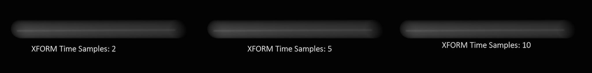
If you have object moving and changing direction extremely quickly, you might want to increase the number of samples to capture the sub-frame direction changes.
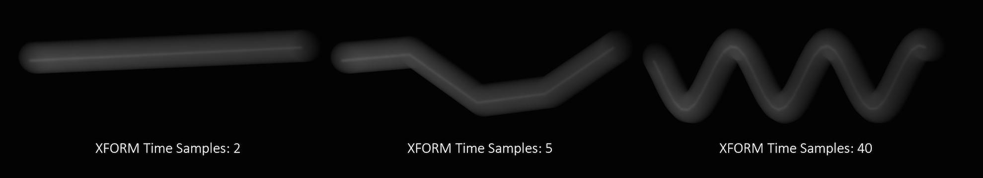
In the above example, it requires 40 transformation samples to correctly render the complex motion that occurs within one frame. (This amount of change within a single frame is very unusual and only used as a demonstration.)
Transformation blur simulates blur by interpolating each object’s transformation between frames, so it’s cheap to compute but does not capture surface deformation. To enable blurring deforming geometry, increase geo_motionsamples.
Geo time samples
The number of sub-frame samples to compute when rendering deformation motion blur over the shutter open time. The default is 1 (sample only at the start of the shutter time), giving no deformation blur by default. If you want rapidly deforming geometry to blur properly, you must increase this value to 2 or more. Increasing the number of geometry time samples is relatively expensive because Houdini must cook the sub-frame geometry and send it to Mantra.
“Deformation” may refer to simple transformations at the Geometry (SOP) level, or actual surface deformation, such as a character or object which changes shape rapidly over the course of a frame.
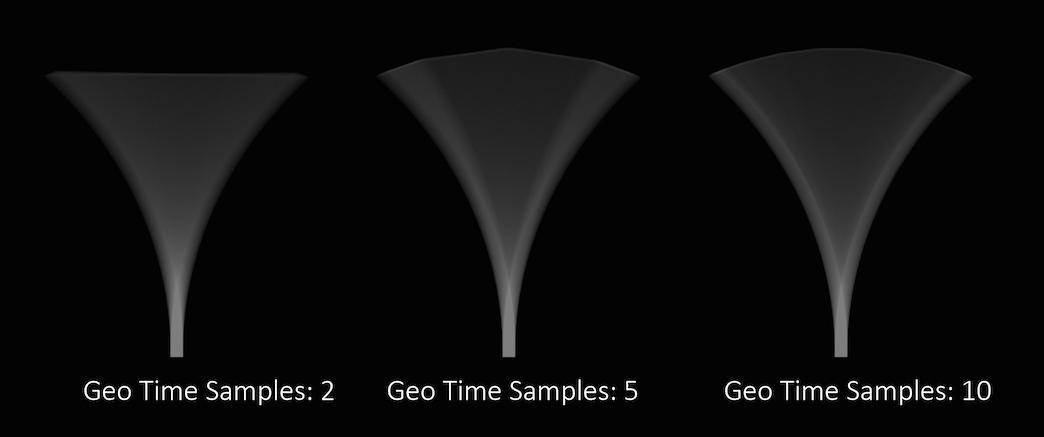
Objects whose deformations are quite complex within a single frame will require a higher number of Geo Time Samples.
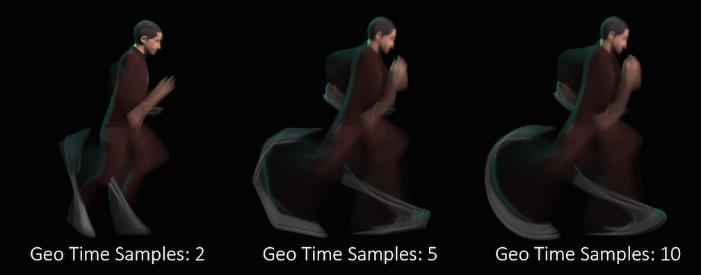
Deformation blur also lets you blur attribute change over the shutter time. For example, if point colors are changing rapidly as the object moves, you can blur the Cd attribute. You must explicitly specify which attributes to blur using the vm_segmentattrs property.
Increasing the number of Geo Time Samples can have an impact on the amount of memory Mantra uses. For each additional Sample, Mantra must retain a copy of the geometry in memory while it samples across the shutter time. When optimizing your renders, it is a good idea to find the minimum number of Geo Time Samples necessary to create a smooth motion trail.
Deformation blur is ignored for objects that have Velocity motion blur turned on.
Shutter offset
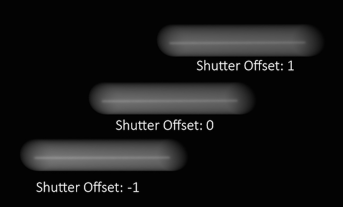
This parameter controls which segment of time will be considered when generating motion blur. A value of 1 will use the current position of the object and the position of the object on the next frame as the time interval to use for motion blur. A value of -1 will use the position of the object on the previous frame and the current position of the object as the time. A value of 0 will generate an interval which lasts halfway through the previous frame and half way into the next frame.
Adjusting this parameter is usually unnecessary unless you are attempting to match motion- blur which has been generated outside of Mantra (for example a photographic background plate).
Controls where the blur occurs in the image relative to the position of the object at the current frame. A value of -1 blurs from the position at the previous frame to the position in the current frame. A value of 0 blurs from halfway to the previous frame to halfway to the next frame. A value of 1 blurs from the current position to the position at the next frame. You can use fractional frame values and values greater than -1 or 1 to move the blur less or more.
To change the size of the blur, change the Shutter time (shutter property).
This parameter replaces the old Motion blur style (motionstyle) parameter, which only allows values of “before” (shutter offset=-1), “center” (shutter offset=0), and “after” (shutter offset=1).
Sampling 
Pixel samples
Controls the number of primary rays Mantra will use to sample your scene per pixel. The two numbers represent an arrangement of samples in the X and Y axis and are generally the same number. However, for non-square pixels it may be necessary to use different values in X and Y. Multiplying these two values together will give you the number of primary rays per pixel.
Increasing Pixel Samples will result in a cleaner, higher quality image. However, since all other sampling values are multiplied by the number of Pixel Samples, they should only be increased when necessary. For more details on when to increase Pixel Samples, see the “Removing Noise” section.
Variance color space
Sampling color space for variance antialiasing. Setting this to Gamma 2.2 will cause darker parts of the image to receive more samples.
Ray variance anti-aliasing
When enabled, this parameter will cause Mantra to use ray variance antialiasing when determining the number of Secondary Rays to send for every Primary Ray.
This means that rather than using a specific number of rays, Mantra will first send out a small number of rays and use this sample set to evaluate the Variance. Depending on the amount of variance, Mantra will continue to send more rays up to the Max Ray Samples value. Ray Variance Antialiasing is useful for optimizing your render by sending more rays only in the areas they are needed.
In cases where the minimum number of rays to remove noise is equal to the maximum number of rays, you may save a small amount of render time by disabling Ray Variance Antialiasing.
Min Ray Samples
This value is the minimum number of secondary rays to use for each BSDF type when generating an image. When Ray Variance anti-aliasing is disabled, this number represents the number of secondary rays to send regardless of the Noise Level.
Remember, this number is multiplied by the current number of Pixel Samples and the number of BSDF types on the material being evaluated.
Max Ray Samples
When Ray Variance anti-aliasing is enabled, this parameter represents the maximum number of secondary rays allowed for each BSDF type even if the Noise Level is never reached. This parameter, along with Min Ray Samples, essentially allows you to create a range of acceptable sampling for your image. Carefully controlling the total number of potential rays is the best way to optimize your renders.
Remember, this number is multiplied by the current number of Pixel Samples and the number of BSDF types on the material being evaluated. For example, if it’s a purely diffuse material, and Pixel Samples are set to 3×3, and the Max Ray Samples is set to 1, then it will cast up to 9 secondary rays (9 diffuse rays). If the material is both reflective and refractive, then it will cast up to 18 secondary rays (9 reflection and 9 refraction rays).
For more details on when to increase Max Ray Samples, see removing noise.
Noise Level
Represents a threshold in the amount of variance allowed before mantra will send more secondary rays. Variance essentially represents how “spread out” the values in a set of samples are. For instance, a set of samples that were all the same would have a variance of 0. It is generally a good idea to keep this value as high as possible so that rays are sent only into those areas where an unacceptable amount of noise is present.
Adding “direct samples” and “indirect samples” image planes can help you track how many samples are being sent and to which parts of the image. For more information about sampling, see the “Sampling and Noise” section.
If you find that certain objects in your scene require substantially more samples than other parts of your image and you are unable to “target” those objects using the Noise Level parameter, it may be a better idea to add per-object sampling parameters to the problem areas. See removing noise for more details.
Diffuse Quality
Controls the quality of indirect diffuse sampling (for information on the difference between direct and indirect rays, see sampling and noise). Often, indirect sources of light (such as the surfaces of other objects, and light scattered inside of a volume) will be a significant cause of noise in your renders. Turning this up should decrease this type of noise, at the cost of slowing down rendering.
This parameter acts as a multiplier on Min Ray Samples and Max Ray Samples and also as a divisor for Noise Level. For example, if you have Min Ray Samples set to 1, Max Ray Samples set to 8 and your Noise Level to 0.1, then set Diffuse Quality to 2, Mantra will send between 2 and 16 secondary diffuse ray samples based on a Noise Level of 0.05. Remember these numbers apply only to the indirect samples. Mantra uses the original values for all direct sampling.
To find how much noise is in your indirect diffuse component, add the “Indirect Lighting (per-component)” image plane in the Extra Image Planes tab. This lets you check each indirect component individually. For this parameter, you should check the Indirect Diffuse component.
Reflection Quality
Controls the quality of indirect reflection sampling (for information on the difference between direct and indirect rays, see sampling and noise). Indirect reflections (reflections of other objects in the scene) can sometimes add noise to the render. Turning this up should decrease this type of noise, at the cost of slowing down rendering.
This parameter acts as a multiplier on Min Ray Samples and Max Ray Samples and also as a divisor for Noise Level. For example, if you have Min Ray Samples set to 1, May Ray Samples set to 8 and your Noise Level to 0.1, then set Reflect Quality to 2, Mantra will send between 2 and 16 secondary reflection ray samples based on a Noise Level of 0.05. Remember these numbers apply only to the indirect samples. Mantra uses the original values for all direct sampling.
To find how much noise is in your indirect reflection component, add the “Indirect Lighting (per-component)” image plane in the Extra Image Planes tab. This lets you check each indirect component individually. For this parameter, you should check the Indirect Reflection component.
Refraction Quality
Controls the quality of indirect refraction sampling (for information on the difference between direct and indirect rays, see sampling and noise). Indirect refractions (refracted light from of other objects in the scene, such as when viewing an object through glass) can sometimes add noise to the render. Turning this up should decrease this type of noise, at the cost of slowing down rendering.
This parameter acts as a multiplier on Min Ray Samples and Max Ray Samples and also as a divisor for Noise Level. For example, if you have Min Ray Samples set to 1, May Ray Samples set to 8 and your Noise Level to 0.1, then set Refract Quality to 2, Mantra will send between 2 and 16 secondary refraction ray samples based on a Noise Level of 0.05. Remember these numbers apply only to the indirect samples. Mantra uses the original values for all direct sampling.
To find how much noise is in your indirect refraction component, add the “Indirect Lighting (per-component)” image plane in the Extra Image Planes tab. This lets you check each indirect component individually. For this parameter, you should check the Indirect Refraction component.
Enable Indirect Sample Limits
Decouples the Direct from Indirect Rays, allowing for different sampling rates as well as separate noise levels. Generally speaking, it will only be necessary to enable this parameter if you find that too many samples are being sent as Direct Rays.
Adding “direct samples” and “indirect samples” image planes can help you track how many samples are being sent and to which parts of the image. For more information about sampling, see the “Sampling and Noise” section.
This parameter will enable three new parameters: Min Indirect Ray Samples, Max Indirect Ray Samples, and Indirect Noise Level.
To understand the difference between Direct and Indirect rays, see sampling and noise.
Volume step rate
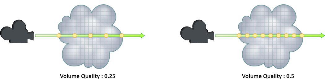
How finely or coarsely a volume is sampled as a ray travels through it. Volumetric objects are made up of 3d structures called Voxels, the value of this parameter represents the number of voxels a ray will travel through before performing another sample.
The default value is 0.25, which means that every one of every four voxels will be sampled. A value of 1 would mean that all voxels are sampled and a value of 2 would mean that all voxels are sampled twice. This means that the volume step rate value behaves in a similar way to pixel samples, acting as a multiplier on the total number of samples for volumetric objects.
For volumes that aren’t voxel based, like CVEX procedural volumes, Mantra will divide the bounding box of the volume into roughly 100 “virtual” voxels. In these cases, setting the Volume Step Rate correctly is essential to maintaining the correct level of detail.
Keep in mind that increasing the volume step rate can dramatically increase render times, so it should only be adjusted when necessary. Also, while increasing the default from 0.25 can reduce volumetric noise, increasing the value beyond 1 will rarely see similar results.
For more information about volume sampling, see sampling and noise.
Volume shadow step rate
A factor to proportionally decrease the volume step rate only for shadows, relative to the volume step rate. Smaller values will cause mantra to use a larger ray march step size for shadow rays than other shading rays. A value of 1 will produce equal quality for shadow rays and shading rays.
Stochastic transparency
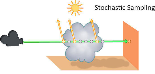
The number of transparent samples to be shaded as a ray travels through translucent objects. Increasing this value will result in less noise in translucent objects and is generally less costly than increasing Pixel samples, Volume Step Rate, or Min and Max ray samples. Stochastic Sampling will not have any effect on noise from Indirect Sources however.
This may make the image noisier than without stochastic transparency, so you may need to compensate by, for example, increasing the pixel samples. You should generally leave this option on.
The renderer ignores this option for micropolygon rendering (except for secondary ray tracing) and for renders that only generate opacity (such as deep shadow maps). In those cases it is more efficient to composite all the transparent shading results.
Added in Houdini 12.
Stochastic samples
The number of transparent samples to shade when Stochastic Transparency is on. Higher values improve shading quality for volumes and transparent surfaces, but are slower to render.
Sample lock
Sampling generally occurs in random patterns which change on every frame of an animation. This can cause a distracting “buzz” when there is a significant amount of noise in your images which can make evaluation of other aspects of the scene difficult. Enabling this parameter will “lock” the sampling patterns so that the noise remains the same on every frame.
Also, in some cases where the final rendered images will be sent through a post-render de- noise process, it can be useful to have the noise remain constant frame to frame. Consistent sampling patterns can help when analyzing the noise.
It defaults to “off” because it is generally unacceptable to have a locked sampling pattern for final sequences.
Random seed
Adjusting this parameter will cause the pixel sampling patterns used by Mantra to be regenerated in different configurations. By default, the patterns change on every frame, so manually changing this value is not necessary.
Allow image motion blur
Occasionally, when motion blur is going to be added to an image as a post-process or for other compositing operations, it is necessary to calculate the motion blur but not include it in the final rendered image. In these cases, Allow Image Motion Blur should be disabled.
This means that the blurred positions necessary for Motion Blur can be exported as a custom Motion Vector Image Plane from within a shader using the GetBlurP() function without the small overhead of doing the actual shading in the render.
This parameter is related to the motion blur parameters which are available only when Motion Blur is enabled. Disabling this option will cause motion blur to be removed from the final rendered image, however the blurred Position will still be calculated, allowing for custom motion vector image planes to be created.
Limits 
Reflect limit
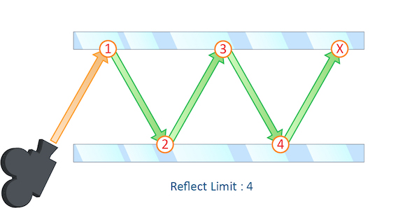
The number of times a ray can be reflected in your scene.
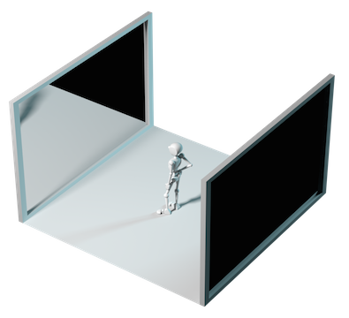
This example shows a classic “Hall of Mirrors” scenario with the subject placed between two mirrors.
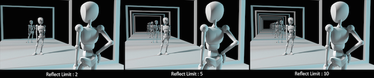
This effectively creates an infinite series of reflections.
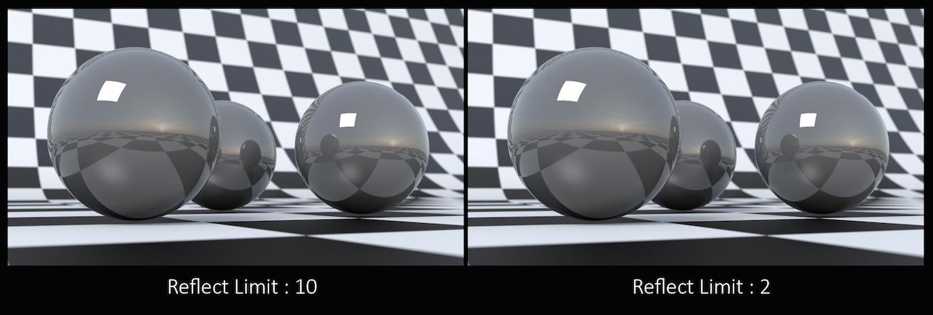
From this camera angle the reflection limits are very obvious and have a large impact on the accuracy of the final image. However, in most cases the reflection limit will be more subtle, allowing you to reduce the number of reflections in your scene and optimize the time it takes to render them.
Remember that the first time a light source is reflected in an object, it is considered a direct reflection. Therefore, even with Reflect Limit set to 0, you will still see specular reflections of light sources.
To control what happens when the maximum number of reflections is exceeded, use At Ray Limit.
Refract limit
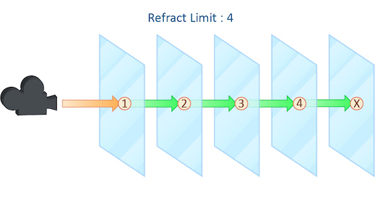
This parameter control the number of times a ray be refracted in your scene.
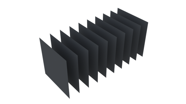
This example shows a simple scene with ten grids all in a row.
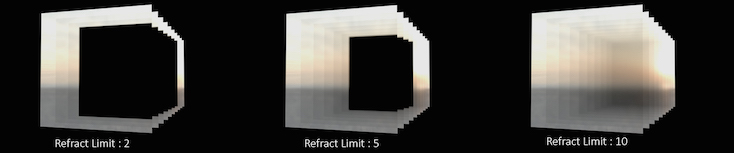
By applying a refractive shader, we will be able see through the grids to an image of a sunset in the background.
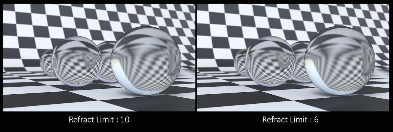
From this camera angle, in order for the image to be accurate, the refraction limit must match the number of grids that that are in the scene. However, most scenes will not have this number of refractive objects all in a row and so it is possible to reduce the refract limit without affecting the final image while also reducing the time it takes to render them.
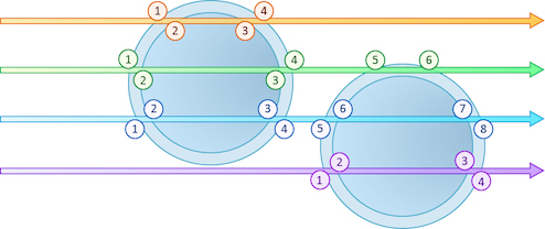
Keep in mind that this Refract Limit refers to the number of surfaces that the ray must travel through, not the number of objects.
Remember that the first time a light source is refracted through a surface, it is considered a direct refraction. Therefore, even with Refract Limit set to 0, you will see refractions of Light Sources. However, since most objects in your scene will have at least two surfaces between it and the light source, direct refractions are often not evident in your final render.
To control what happens when the maximum number of refraction is exceeded, use At Ray Limit.
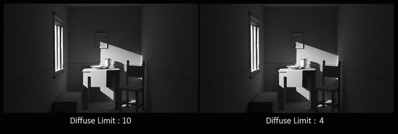
Diffuse limit
The number of times diffuse rays can propagate through your scene.
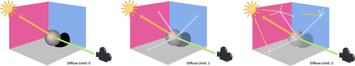
Unlike the Reflect and Refract Limits, this parameter will increase the overall amount of light in your scene and contribute to the majority of global illumination. With this parameter set above zero diffuse surfaces will accumulate light from other objects in addition to direct light sources.
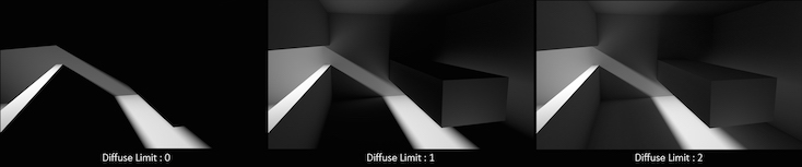
In this example, increasing the Diffuse Limit has a dramatic effect on the appearance of the final image. To replicate realistic lighting conditions, it is often necessary to increase the Diffuse Limit. However, since the amount of light contribution usually decreases with each diffuse bounce, increasing the Diffuse Limit beyond 4 does little to improve the visual fidelity of a scene. Additionally, increasing the Diffuse Limit can dramatically increase noise levels and render times.
Volume limit
The number of times a volumetric ray can propagate through a scene. It functions in a similar fashion to the Diffuse Limit parameter.
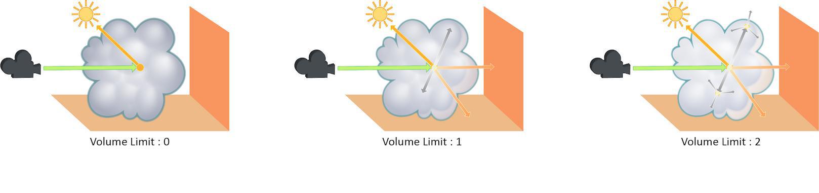
Increasing the Volume Limit parameter will result in much more realistic volumetric effects. This is especially noticeable in situations where only part of a volume is receiving direct lighting. Also, in order for a volumetric object to receive indirect light from other objects, the Volume Limit parameter must be set above 0.
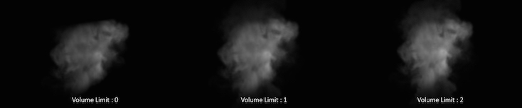
With the Volume Limit set to values above zero, the fog volume takes on the characteristic light scattering you would expect from light traveling through a volume. However, as with the Diffuse Limit, the light contribution generally decreases with each bounced ray and therefore using values above 4 does not necessarily result in a noticeably more realistic image.
Also, increasing the value of this parameter can dramatically increase the amount of time spent rendering volumetric images.
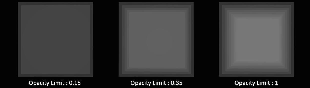
Opacity limit
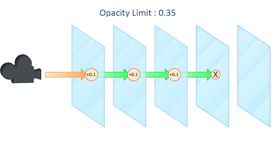
As a ray travels through many transparent surfaces, or through a volume, it will calculate the cumulative amount of Opacity. When this value exceeds the Opacity Limit mantra will assume all surfaces beyond this point are opaque.
This parameter behaves in a similar fashion to both the Reflect and Refract Limit but operates on accumulated values rather than simply the number of surfaces the ray has passed through.
In this example, each grid has a shader attached with an opacity value of 0.1. It is important to remember that in this case “transparent” refers to objects whose opacity is less than 100% and does not include refractive objects which can appear transparent.
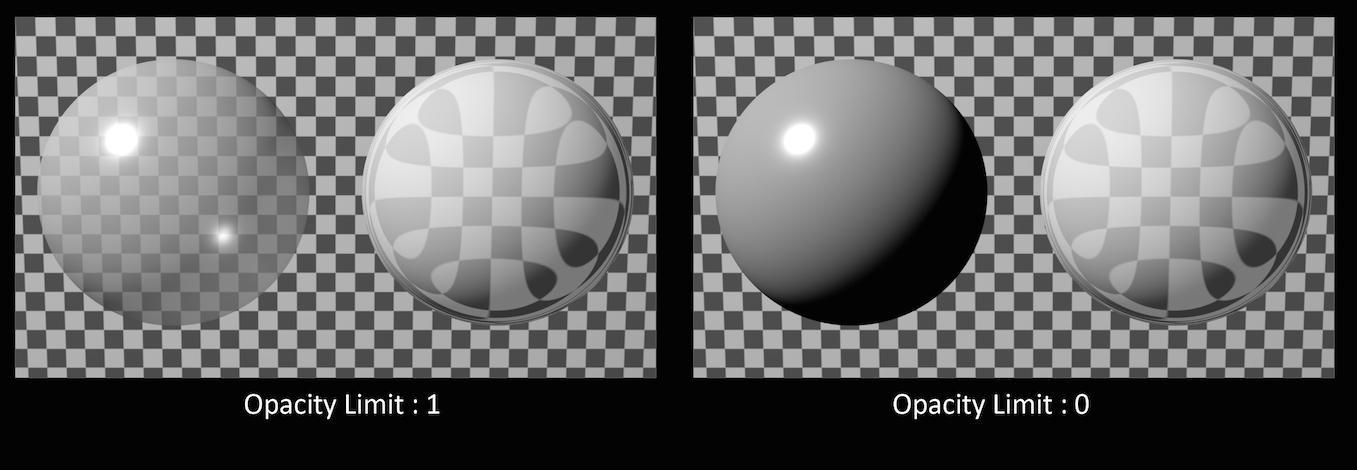
In this example, the sphere of the left has an opacity of 0.5, with no refraction. The sphere on the right has an Opacity of 1 with refraction enabled. You can see that the Opacity Limit has no effect on the amount of refraction, only affecting objects whose opacity value is less than 1.
While reducing the Opacity Limit may save a small amount of render time (1 – 5%) using low values may result in banding and other artifacts when your camera is moving or an animation is evolving. This can be especially noticeable in smoke simulations where opacity values are constantly changing.
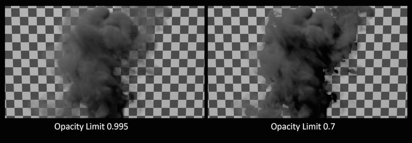
The default value for Opacity Limit is quite aggressive, changing this value should be done carefully and the results inspected across a range of frames in an animated sequence.
Color limit
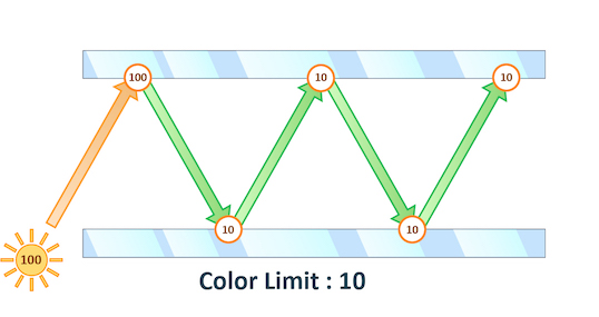
The maximum value a shading sample is allowed to return from indirect sources. When rendering using PBR the path’s total illumination is also constrained.
Physically Based Rendering can cause “spikes” in color values when extremely bright indirect light sources are under sampled. This results in “fireflies” in the final rendered image which can be very difficult to remove without very high sampling rates.
You can see in this example that even at 12×12 pixel samples, the “fireflies” still remain. Adjusting Min and Max indirect rays sample settings could remove this noise, but at the cost of longer render times.
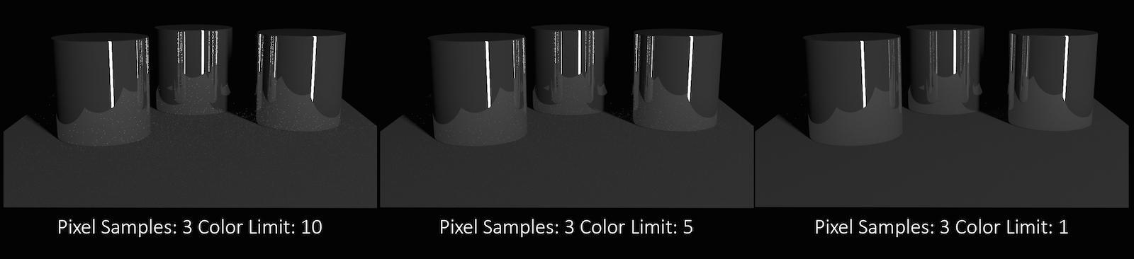
Decreasing the Color Limit parameter clamps the color values in these indirect samples and can help to avoid these “spikes”.
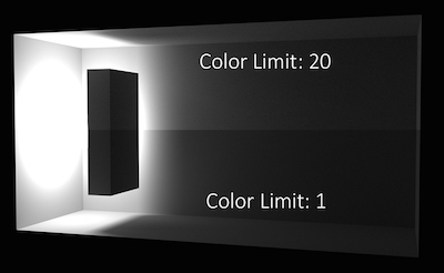
Reducing the color Limit can be an effective way of removing “fireflies” without increasing sampling rates. However, clamping the values in indirect lighting can result in an overall reduction in the amount of light in your scene. This is especially evident in scenes which are mostly illuminated by indirect light.
At ray limit
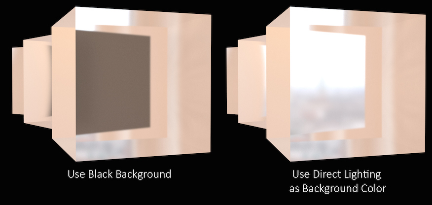
Controls how Mantra deals with rays that reach the ray tracing limit (For example the Reflect Limit or Refract Limit).
In this example, the refract Limit has been set to 2.
Setting At Ray Limit to Use Black Background will simply render black once the limits are reached. This is the default setting and will work in most scenes since the Reflect or Refract Limit is unlikely to be reached. However, in scenes where the limit is noticeable in the rendered image, the black color can be quite noticeable and stand out against the colors in the scene.
In this case, increase the limit until the effect is avoided or use the Use Direct Lighting as Background Color option. This will replace the black color with whichever color or image is used in your direct lighting, for instance an Environment Light.
For More Information about how the settings on an Environment Light affect this parameter see lighting.
Shading 
Raytracing bias
Global raytracing bias to be used for PBR rendering, specified in world space units. Increase the raytracing bias only if doing so eliminates rendering artifacts in your render. For really small scenes (1 unit in size), it is sometimes necessary to decrease the raytracing bias.
Bias along normal
When biases are used in VEX shaders, the bias can either be performed along the ray direction or along the surface normal. If this parameter is turned on, biasing will be along the surface normal - using the Ng VEX variable.
If the ray direction and normal point in different directions, the normal will first be flipped and then biasing will be performed in the direction of the flipped normal. This setting is particularly useful when ray traced surfaces that are seen edge-on.
Enable Absorption and Nested Dielectrics
To save on computation, mantra will only compute exports on surface shaders if the variable needs to be saved to an image plane. This means that some surface exports may not be available in fog shaders for the simport() function. However, to properly render advanced features like absorption and nested dielectrics, additional exports from surface shaders are required. This enables on these special exports.
Allowable paths
The type of path tracing to perform in PBR mode.
specular, diffuse
Trace all diffuse and specular bounces, but once a diffuse bounce is encountered continue tracing only with diffuse reflections.
all
All paths are traced. This option can be used to enable rendering of caustics without the use of photon maps. However when using point or small area lights, the rendered result can turn out to be extremely noisy.
Constrain by Maximum Roughness
Roughness parameter in GGX BSDFs are clamped by the maximum roughness value propagated down the ray chain in pathtracing. Enabling this option can cut out a lot of noise in indirect specular (in particular, cases where glossy surface is reflected by a rough specular surface) at the cost of a bit of accuracy.
Refract Components
A space-separated list of component types that will behave like refract bounces. This will affect which reflection scope is used based on the ray type and also which bounce limit to use. Uncategorized component types are assumed to be reflections.
Diffuse Components
A space-separated list of component types that will behave like diffuse bounces. This will affect which reflection scope is used based on the ray type and also which bounce limit to use. Uncategorized component types are assumed to be reflections.
Volume Components
A space-separated list of component types that will behave like volume bounces. This will affect which reflection scope is used based on the ray type and also which bounce limit to use. Uncategorized component types are assumed to be reflections.
SSS Components
A space-separated list of component types that will behave like subsurface scatter bounces. This will affect which reflection scope is used based on the ray type and also which bounce limit to use. Uncategorized component types are assumed to be reflections.
Render 
Tile size
The size (in pixels) of the tiles rendered by mantra. Larger tile sizes may consume more memory.
Use max processors
When enabled, automatically set the thread count (renderer:threadcount IFD property) to the number of CPUs of the rendering machine.
Thread count
When Use Max Processors (renderer:usemaxthreads IFD property) is disabled, sets the number of threads Mantra uses for rendering.
Cache Limit
Whether to use a fixed size cache (vm_cachesize) or whether to use a proportion of physical memory (vm_cacheratio)
Cache Memory Ratio
The proportion of physical memory Mantra will use for its unified cache.
For example, with the default vm_cacheratio of 0.25 and 16 Gb of physical memory, Mantra will use 4 Gb for its unified cache.
The unified cache stores dynamic, unloadable data used by the render including the following:
-
2D
.rattexture tiles -
3D
.i3dtexture tiles -
3D
.pcpoint cloud pages (when not preloaded into memory) -
Tessellated meshes required by ray tracing:
-
Displacements
-
Subdivision surfaces
-
Bezier and NURBS primitives
-
Ray tracing accelerator
Controls the type of ray tracing accelerator used by mantra. A ray tracing accelerator is a spatial data structure used to optimize the performance of ray intersection tests against complex geometry.
KD-Tree ("kdtree")
Ray trace using a KD-Tree. Normally, the KD-Tree will produce the fastest raytracing performance at a modest initialization time. It is possible to control the performance/quality tradeoff for KD-Tree construction with the KD-Tree Memory Factor parameter (vm_kdmemfactor).
Bounding Volume Hierarchy ("bboxtree")
Ray trace using a bounding volume hierarchy. Sometimes a bounding volume hierarchy will be faster to construct and/or faster to raytrace than a KD-Tree.
KD-Tree memory factor
Change the memory/performance tradeoff used when constructing KD-Tree acceleration data structures. Values larger than 1 will cause mantra to use proportionally more memory and take longer to optimize the tree in an attempt to make ray tracing faster. Smaller values will cause mantra to use proportionally less memory and take less time to optimize the tree, while possibly compromising ray tracing performance. The default value of 1 will try to balance the amount of memory used by ray tracing data structures with the amount of memory used by geometry.
If you are noticing long tree construction times, try decreasing the KD memory factor to 0.1. If your render is too slow after tree construction, increase the value until you find a good balance of tree construction time vs. render performance.
UV Attribute
When texture baking to UDIM images, this is the name of the texture coordinate attribute used for unwrapping.
Output OTLs with full paths
Enabling this checkbox will expand any variables in OTL paths, breaking the dependency on Houdini environment variables, but possibly making the IFD less portable.
Force VEX shader embedding
Mantra is able to load the shader directly from the OTL when Houdini uses a shader defined in an OTL. When shaders are built using VOPs, the shader must be embedded in the IFD. Enabling this option will force Houdini to embed the shaders defined by OTLs.
This option makes the IFD more self-contained so that machines which don’t have the OTL installed (or a different version of the OTL) are able to evaluate the shaders correctly.
However, if you have complicated shaders, embedding them will bloat the size of the IFD significantly.
Output OTLs with full paths
Enabling this checkbox will expand any variables in OTL paths, breaking the dependency on Houdini environment variables, but possibly making the IFD less portable.
Declare style sheets
Controls which style sheets defined in the hip file are embedded into the IFD. Standard Houdini pattern matching is used on each embedded style sheet name.
Apply style sheets
Specifies which style sheets mantra should apply during rendering. This is a space separated list of either names of style sheets embedded in the hip file, or external JSON files on disk. As with individual styles within a single style sheet, style sheets later in the list take precedence over style sheets earlier in the list.
Declare materials
Controls which SHOPs are embedded in the generated IFD. This parameter can be used to force all SHOPs or all Material SHOPs to be embedded even if Houdini does not find explicit references to those SHOPs on the output objects and geometry.
Dicing 
Shading quality multiplier
A global multiplier on all per-object shading quality (vm_shadingquality) parameters in the scene. This parameter can be used to globally increase or decrease shading quality. The shading quality used for an object is determined by…
shadingquality = object:shadingquality * renderer:shadingfactor
Motion factor
Fast moving objects which have significant amounts of motion blur are rendered with the same sampling quality as slow moving or static objects. However, in cases where objects are very blurry, small details are usually lost. In these cases, it is a useful optimization to reduce the shading quality on those objects which are moving quickly since the loss in detail is hidden in the motion blur.
Increasing the Motion Factor will dynamically reduce the shading quality of an object based on the rate of motion. This optimization is primarily useful for objects which are refined at render time like subdivision surfaces or objects with displacement-based shading.
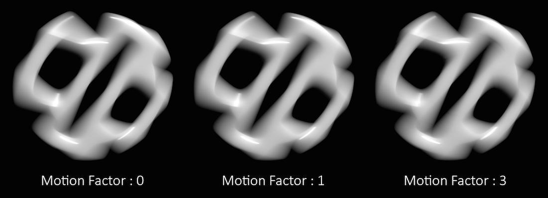
In the above example, you can see that the motion factor does not have a large impact on the quality of the final render.
However, sometimes too much detail can be lost, especially in cases where much of the surface detail is generated by the shader. Objects whose shape is derived through significant amounts of displacement, for example.
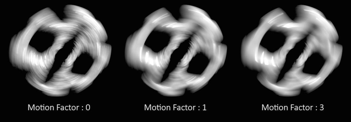
In these cases, the Motion Factor value must be adjusted carefully to retain a believable amount of surface detail.
Note
The exact motion factor used will depend on the degree of motion in your scene. For more information, see Motion factor on the mantra rendering properties page.
Automatically adjusts the shading quality for objects which are significantly blurred. Increasing the motion factor of an object will dynamically decrease the shading quality based on the rate of motion. This can significantly speed up renderings of rapid moving objects. It also affects depth of field and may improve speed of scenes with deep depth of focus.
Motion factor reduces shading quality using the following formula:
new_shading_quality = shading_quality / max(motion_factor * pixels_of_motion/16, 1)
This is only true if motion_factor > 0.
Objects traveling more than 16 pixels within the frame will have their shading quality reduced by the above factor. For example, an object blurred over 32 pixels with a shading quality of 1 will have the quality reduced to 0.5. You should not use very large values for this parameter. Values between 0 and 1 are reasonable.
When using the Ray Tracing or Physically Based Rendering rendering engine, motion factor will only affect the geometric subdivision for subdivision surfaces, NURBS/Beziers, or displacements and will not change the amount of shading.
Geometry measuring
When primitives are rendered in mantra, they are split into smaller primitives if they are too big to be rendered. The primitives are measured to determine if they are too big using the measurer.
There are several different measurers available, each which take some optional arguments.
Non-Raster Measuring (nonraster [-z importance])
This measures geometry in 3D. The Z-Importance can be used to bias the z-component of the surface. A Z-Importance of 0 means that the x and y components of the object will be the only metric in determining the size of the object. This is roughly equivalent to raster space measurement.
By increasing the Z-Importance to 1, the z measurement becomes more meaningful. It is possible to increase the Z-Importance beyond 1.
If you think of a grid in the XY plane, the z-importance has no effect. However, if the grid is nearly in the XZ plane, z-importance has more influence on the dicing. With a Z-Importance of 0, only the projected measurements will be used, which will result in long, thin strips being created. With a Z-Importance of 1, the grid will be more uniformly sub-divided. With a value greater than 1, more divisions will be performed in Z.
This is important when displacement mapping is being performed. Increasing the Z-Importance will improve quality on displacement shaded ground planes (for example). The default value of 1 generally will result in sharp, high quality displacements at a shading quality of 1 for all incident angles.
This is mantra’s equivalent to prman’s raster-orient flag.
Raster Space Measuring (raster)
Measures geometry in screen space. This is roughly equivalent to the "nonraster -z 0" measurer, so is deprecated in favor of that approach.
Uniform Measuring (uniform)
Generates uniform divisions. The size of the divisions is controlled by the Geometry Quality or Shading Quality in micropolygon renders.
Z-importance
This parameter controls the z-importance for nonraster measuring. See vm_measure above.
Offscreen Quality
This parameter controls the shading quality scale factor for geometry that is not directly visible to the camera. For geometry that is outside the field of view (ie. visible only to secondary rays), mantra will smoothly reduce the shading quality based on the angle between the geometry and the edge of the viewing frustum. Smaller values can increase performance particularly in scenes where the camera is within the displacement bound of nearby geometry, where it permits the hidden primitives to be diced more coarsely than those that are directly visible.
Objects 
The parameters on this tab determine which objects and lights are included in the IFD.
Mantra processes these parameters in the following order:
-
Candidate objects/lights are selected.
-
Forced objects/lights are added.
-
Objects/Lights matching the exclusion parameter are removed.
Candidate Objects
The geometry objects in this parameter will be included in the IFD if their display flags are turned on and their display channel is enabled.
Force Objects
Objects in this parameter are added to the IFD regardless of the state of their display. Objects can only be added to the IFD once.
Forced Matte
Objects forced to be output as matte objects.
Forced Phantom
Objects forced to be output as phantom objects.
Exclude Objects
Objects in this parameter are excluded from the scene, regardless of whether they are selected in the Candidate Objects or Force Objects.
Solo Light
Only lights in this parameter will be included in the IFD. This includes shadow map generation and illumination. If this parameter is set, the candidate, forced, and exclusion parameters are ignored.
Using this parameter in conjunction with the render_viewcamera property provides a quick way of generating shadow maps for selected lights.
Candidate Lights
Each light in this parameter is added to the IFD if the dimmer channel of the light is not 0. The standard light sets the dimmer channel to 0 when the light is not enabled.
Force Lights
The lights in this parameter are added to the IFD regardless of the value in their dimmer channels.
Exclude Lights
These lights will be excluded from the scene, even if they are selected in Candidate Lights or Force Lights__.
Headlight Creation
If there are no lights in the scene, a headlight is created by default. To disable, turn off this checkbox.
Visible Fog
The fog/atmosphere objects in this parameter are included in the IFD if their display flags are turned on and their display channel is enabled.
Scripts 
Each script command refers to an hscript command which will be run, regardless of the expression language selected for the parameter. The resulting string will be run as an hscript command. It is possible to use the python, unix or source hscript commands to perform complex processing.
The commands are always run when rendering occurs. The command checks the parameters of the output driver when it is rendering a range or sending output to a command.
Before the render occurs, Houdini will automatically set the current hscript directory to point to the output driver.
Pre-Render Script
This command is run before any IFDs are generated. It is only run once per render.
Pre-Frame Script
This command is run before each IFD is generated.
Post-Frame Script
This command is run after each IFD is generated. Although the IFD may have been generated, this does not necessarily mean that mantra has finished rendering the image when this command is run.
Post-Render Script
This command is run one time, after all IFDs have been generated. Although the IFD may have been generated, this does not necessarily mean that mantra has finished rendering the image when this command is run.
Driver 
Command
The command (i.e. mantra) where the IFD file is sent. This will be disabled if the IFD file is saved to disk.
Note
The Mantra ROP will not automatically gzip based on the file extension of the .ifd file. The file .ifd.gz will contain uncompressed data. However, you can set your render command to something like gzip > foo$F4.ifd.gz to compress the file.
Disk File
The location where the IFD file is saved to disk. You must turn on the Disk File checkbox to enable this parameter.
Wait for Render to Complete
When sending the output to a command, Houdini will normally return control after it is finished writing the IFD. This allows the render process to complete in the background. Turning on this parameter will force Houdini to block until the mantra finishes rendering the frame.
When rendering a frame range, this option is automatically turned on. However, the option is not automatically turned on when rendering in an hscript or python loop construct. Therefore caution must be used or it is possible to end up starting multiple background renders.
Note
The rps and rkill hscript commands can be used to query or kill background renders.
See the Troubleshooting section for more information.
Initialize Simulation OPs
If this option is turned on, POP and DOP simulations will be initialized before rendering.
Show In Viewport
Enabling this checkbox will cause the driver to show up in the viewport menu. By default, SOHO output drivers to not appear in the viewport menu.
Save Binary Geometry
Saves binary geometry in the IFD. If this option is turned off, ASCII geometry is saved in the IFD. Binary is much more efficient. ASCII is readable.
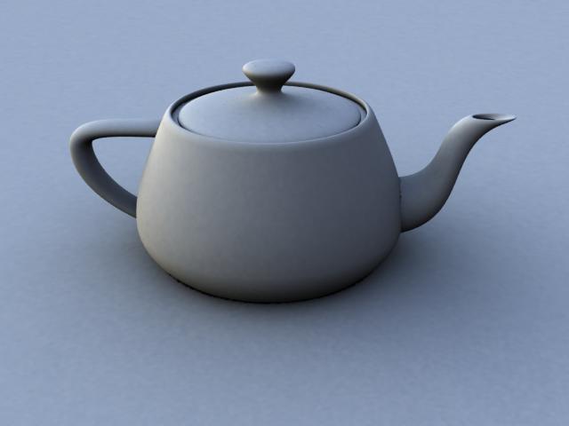
Examples 
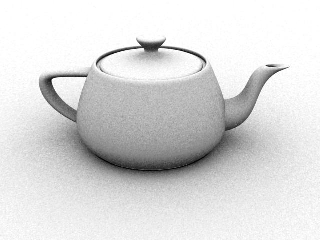
AmbientOcclusion Example for Mantra render node
Ambient occlusion is a fast technique for producing soft, diffuse lighting in open spaces by using ray tracing. It is computed by determining how much of the hemisphere above a point is blocked by other surfaces in the scene, and producing a darker lighting value when the point is heavily occluded. This technique can be useful when you need a GI-like effect without paying the price for full global illumination.
With this particular example, an Ambient Occlusion light and some geometry is provided in the form of a Digital Asset. An Environment Light was used, and it’s parameters were promoted for easy access.

Decreasing the sample count allows you to improve render time at the expense of some additional noise in the render. The following render uses the same shader as the image above but decreases the samples from the default of 256 to 16. This value is set on the Sampling Quality under the Render Options tab of the Light.
Environment Maps
If you have a smooth environment map, it is possible to replace the global background color (white) with the value from an environment map. You can also enable the Sky Environment Map under the Sky Environment Map tab.
MotionVector Example for Mantra render node
The example demonstrates how to generate a motion vector layer for post-velocity compositing. Load the example and render 5 frames. Then in the image viewer, switch from 'C' (colour) to 'motion_vector' to see the results.
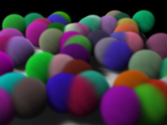
Volume Rendering - Metaballs as Volume Example for Mantra render node
Metaball geometry can be natively rendered as a volume in mantra. Metaball rendering can be enabled by checking the Metaballs as Volume parameter on the Geometry tab of a geometry object. Any point attributes on the metaballs will be interpolated to the shading position in the same manner that point attributes are interpolated for metaball surfaces.
Here is an example using randomized point color attributes:
Controlling Shadow Quality/Performance
Shadow map generation uses the Pixel Samples and Shadow Step Size parameters (in the Mantra Render Operator) to control quality and performance in exactly the same way they are used for surfaces. Since volumes often cast soft, diffuse shadows, it is often possible to use low-resolution deep shadow maps when rendering volumes, leading to much faster render times. Shadow map Resolution can be changed on the Shadow tab of a Houdini light.
Volume Rendering - File Referenced Smoke Example for Mantra render node
Volume rendering is a rendering approach that allows high-quality, integrated rendering of volumetric effects like smoke, clouds, spray, and fire.
Volume rendering is suitable for rendering many types of volumetric effects. Scenes that are particularly suited to rendering with mantra volumes include:
-
Detailed “hero” clouds, smoke, or fire
-
Fields of instanced clouds, smoke, or fire
Scenes where volume rendering may not be quite so applicable include:
-
Scenes with a single uniform fog
In this particular example, a bgeo file (1 frame only) was exported from a fluid simulation of smoke and is now referenced using the File SOP. A material using VEX Volume Cloud is assigned to this volumetric data at the top level of the Volume Object. To see this scene in shaded mode, ensure that HOUDINI_OGL_ENABLE_SHADERS is set to 1 in the environment variables.
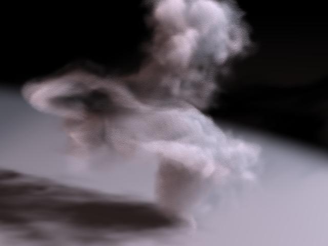
Controlling Quality/Performance 
Volume rendering uses ray marching to step through volumes. Ray marching generates shading points in the volume by uniformly stepping along rays for each pixel in the image. There are two ways to change the quality and speed of the volume ray marching:
-
The samples parameter on the Sampling tab of the mantra ROP. More pixel samples will produce more ray marches within that pixel leading to higher quality. Using more pixel samples will also improve antialiasing and motion blur quality for the volume.
-
The volumesteprate parameter on the Sampling tab of the mantra ROP. A larger volume step rate will produce more samples in the volume interior, improving quality and decreasing performance. A separate shadow step rate can be used for shadows.
Which parameter you should change will depend on your quality requirements for pixel antialiasing. In general, it is better to decrease the volume step size rather than increase the pixel samples because a smaller volume step size will lead to more accurate renders.
This render uses 2×2 samples and volume step rate of 1. Notice the detail in the shadows.
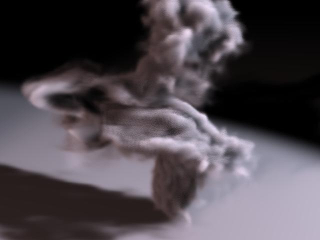
This render uses the same scene with 4×4 samples and a volume step rate of 0.25. The fine detail in the shadow has been lost and the volume is somewhat more transparent. The quality level is approximately the same.
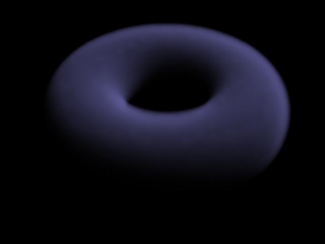
Volume Rendering - From Primitives Example for Mantra render node
Volume rendering is a rendering approach that allows high-quality, integrated rendering of volumetric effects like smoke, clouds, spray, and fire.
Volume rendering is suitable for rendering many types of volumetric effects such as:
-
Detailed “hero” clouds, smoke, or fire
-
Fields of instanced clouds, smoke, or fire
It is easy to create volumes from primitives without invoking the fluid solver.
In this particular example, a primitive torus is used to render some smoke volume. Using an IsoOffset SOP produces a volume that fills the interior of the torus. Then, a material using a Volume Cloud is assigned to the volumetric data of the torus shape. Setting the Smoke Cloud Density to 5 and the Smoke Shadow Density to 10 helps create a more smoke-like look and feel.
Here is the torus rendered with tweaks to the volume step sizes (in the Mantra Render Operator), shadow map quality (under Depth Map Options of the spotlight), and volume primitive divisions (on the IsoOffset SOP). The smoke Diffuse color was adjusted too.
| See also |