| On this page |
|
Overview 
These properties control rendering in mantra. They are in the mantra folder in the list of properties available under the Render Properties tab of the Edit parameter interface window. Select a node, and in the parameter editor click the ![]() Gear menu and choose Edit rendering properties to add or remove properties to a render driver, camera, object, shader, or properties node.
Gear menu and choose Edit rendering properties to add or remove properties to a render driver, camera, object, shader, or properties node.
Note
All command line options to mantra (except -H and -P) now have property equivalents, so you can add them to the driver node instead of specifying them on the command line.
For advanced users, to get a complete list of all properties defined in mantra (including undocumented properties), you can run the ray_show command in mantra. For example:
echo ray_show object | mantra
echo ray_show renderer | mantra
Note
Mantra reads default values from the RenderProperties.json file at startup (unless the -D option is specified). This can let studios change mantra’s default values for properties.
Warning
Any undocumented properties may change at any time and may not be fully supported.
Properties 
Deep Output 
When generating an image, mantra runs the sample filter to composite samples to a single color. Mantra then runs the pixel filter to produce the final color for a pixel. A deep resolver is used to store information about each sample prior to sample filtering. This allows the image resolver to store information about each individual sample before compositing.
If you want to change the vm_deepresolver through Python, you have to specify one of the three tokens to represent the available modes: null, shadow, camera.
No Deep Resolver
Deep image will not be output.
Deep Shadow Map
Only the opacity (Of) and depth (Pz) image planes will be written out.
Deep Camera Map
All planes selected for deep images will be written out. Use Exclude from DCM to leave a specific image plane from the deep image output.
Deprecated in Houdini 14.5. Specifies how each pixel sample should be interpreted. Unlike some other deep image formats, mantra only writes out a single depth value for each sample.
discrete
Each depth sample represents a discrete surface.
continuous
Each depth sample is part of a continuum (i.e. volume).
Compression value between 0 and 10. Used to limit the number of samples which are stored in a lossy compression mode for volume samples. The compression parameter applies to opacity values, and determines the maximum possible error in opacity for each sample. For compression greater than 0, the following relationship holds: OfError = 1/(2^(10-compression))
The samples stored in the deep file can be stored as either uncomposited, meaning that each sample is independent of any other sample for the same pixel; or it can be stored pre-composited, meaning that each sample stores the accumulated opacity of the sample behind it and the opacity of the sample itself.
Force DCM Pixel Filter on Image Planes
When rendering DCM, force regular/non-deep image planes to have the same pixel filtering as DCM’s (i.e. Unit Box filter).
Specifies the amount of bits to use to store opacity samples. The default is 16 bits. Larger values may cause the file size to increase substantially, with little gain in fidelty.
Specifies the amount of bits to use to store opacity samples. The default is 32 bits. Smaller values may cause unnecessary discretization of samples of sample far away from the camera, but can save substantially on file size.
Used in compression to merge together samples which are closer than the given threshold. Samples that are closer together than this bias value, are merged into a single sample and stored at the average z value of all the merged samples.
Opacity is usually computed as a full-color value and stored as such. To cut down on file size, if full color is not needed, this settings can be used to store a monochromatic version of the full color value.
Monochrome:
The opacity is stored as a single, grayscale channel.0
Full Color:
The opacity is stored with full red, green and blue separation.
Deprecated in Houdini 14.5. Used in compression to determine whether to keep the nearest, the farthest or the midpoint of samples.
Nearest sample
Choose the smallest Pz value.
Midpoint sampling
Choose the midpoint of Pz values.
Farthest sample
Choose the largest Pz value.
Deep camera images can contain several “special” image planes. These can be used to improve compositing of deep images. The special planes currently recognized are:
zfront
The z value of the depth sample.
zback
For volume samples, this specifies the farthest extent of the sample.
deepcover
Store sample coverage as a bit mask.
deepflags
Store flags indicating whether the shading sample is a volume or a matte surface.
Whether to create MIP mapped images for deep camera images.
By default, MIP maps are not created for deep camera images, since deep camera images tend to be used for deep compositing (which doesn’t require MIP maps).
See DCM Filename for details.
See DCM Interpolation for details.
See DCM Compression for details.
See DCM Pre-Composite Samples for details.
Mantra expects deep shadow images to be pre-composited. If you use un-composited shadow maps, rendering may be slower or generate bad results.
See DCM Of Storage for details.
See DCM Z Storage for details.
See DCM Z-Bias for details.
See DCM Of Size for details.
See DCM Z-Sample Filter for details.
Deep shadow images can contain several “special” image planes. These can be used to improve compositing of deep images. The special planes currently recognized are:
zfront
The z value of the depth sample.
zback
For volume samples, this specifies the farthest extent of the sample.
deepcover
Store sample coverage as a bit mask.
deepflags
Store flags indicating whether the shading sample is a volume or a matte surface.
These special channels are discussed in: Improved Deep Compositing
Cryptomatte 
The number of cryptomatte layers to output. This must be set to 1 or higher to enable the cryptomatte resolver. The cryptomatte resolver is used to store the ID (based on hash of user-specified string property) and opacity pair of each sample prior to sample filtering.
Property to generate IDs from. materialname and name are built-in property names for material path and object path respectively. It can also be any object property of string type, including user property.
Maximum number of IDs that can be stored in a single pixel. A value of 6 is recommended.
Output path of the cryptomatte layer. OpenEXR format recommended. If this path is not specified, then this layer will be stored along with primary output. It’s also possible to have multiple layers with identical Different File path to write a cryptomatte image with multiple layers, but Channel Name should be unique to avoid confusion (a temporary channel name will be generated if more than one layer tries to write to same file with identical channel name).
Dicing 
A global multiplier on all per-object shading quality (vm_shadingquality) parameters in the scene. This parameter can be used to globally increase or decrease shading quality. The shading quality used for an object is determined by…
shadingquality = object:shadingquality * renderer:shadingfactor
This parameter controls the geometric subdivision resolution for all rendering engines and additionally controls the shading resolution for micropolygon rendering. With all other parameters at their defaults, a value of 1 means that approximately 1 micropolygon will be created per pixel. A higher value will generate smaller micropolygons meaning that more shading will occur - but the quality will be higher.
In ray tracing engines, shading quality only affects the geometric subdivision quality for smooth surfaces (NURBS, render as subdivision) and for displacements - without changing the amount of surface shading. When using ray tracing, pixel samples and ray sampling parameters must be used to improve surface shading quality.
The effect of changing the shading quality is to increase or decrease the amount of shading by a factor of vm_shadingquality squared - so a shading quality of 2 will perform 4 times as much shading and a shading quality of 0.5 will perform 1/4 times as much shading.
When rendering a curve, turns the curve into a surface and dices the surface, running the surface shader on multiple points across the surface. This may be useful when the curves become curved surfaces, but is less efficient. The default is to simply run the shader on the points of the curve and duplicate those shaded points across the created surface.
Fast moving objects which have significant amounts of motion blur are rendered with the same sampling quality as slow moving or static objects. However, in cases where objects are very blurry, small details are usually lost. In these cases, it is a useful optimization to reduce the shading quality on those objects which are moving quickly since the loss in detail is hidden in the motion blur.
Increasing the Motion Factor will dynamically reduce the shading quality of an object based on the rate of motion. This optimization is primarily useful for objects which are refined at render time like subdivision surfaces or objects with displacement-based shading.
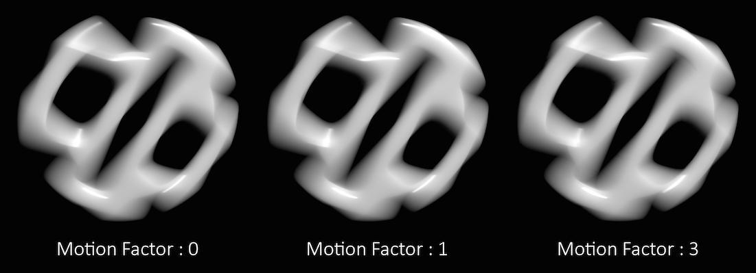
In the above example, you can see that the motion factor does not have a large impact on the quality of the final render.
However, sometimes too much detail can be lost, especially in cases where much of the surface detail is generated by the shader. Objects whose shape is derived through significant amounts of displacement, for example.
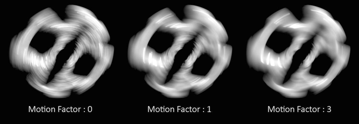
In these cases, the Motion Factor value must be adjusted carefully to retain a believable amount of surface detail.
Note
The exact motion factor used will depend on the degree of motion in your scene. For more information, see Motion factor on the mantra rendering properties page.
Automatically adjusts the shading quality for objects which are significantly blurred. Increasing the motion factor of an object will dynamically decrease the shading quality based on the rate of motion. This can significantly speed up renderings of rapid moving objects. It also affects depth of field and may improve speed of scenes with deep depth of focus.
Motion factor reduces shading quality using the following formula:
new_shading_quality = shading_quality / max(motion_factor * pixels_of_motion/16, 1)
This is only true if motion_factor > 0.
Objects traveling more than 16 pixels within the frame will have their shading quality reduced by the above factor. For example, an object blurred over 32 pixels with a shading quality of 1 will have the quality reduced to 0.5. You should not use very large values for this parameter. Values between 0 and 1 are reasonable.
When using the Ray Tracing or Physically Based Rendering rendering engine, motion factor will only affect the geometric subdivision for subdivision surfaces, NURBS/Beziers, or displacements and will not change the amount of shading.
When primitives are rendered in mantra, they are split into smaller primitives if they are too big to be rendered. The primitives are measured to determine if they are too big using the measurer.
There are several different measurers available, each which take some optional arguments.
Non-Raster Measuring (nonraster [-z importance])
This measures geometry in 3D. The Z-Importance can be used to bias the z-component of the surface. A Z-Importance of 0 means that the x and y components of the object will be the only metric in determining the size of the object. This is roughly equivalent to raster space measurement.
By increasing the Z-Importance to 1, the z measurement becomes more meaningful. It is possible to increase the Z-Importance beyond 1.
If you think of a grid in the XY plane, the z-importance has no effect. However, if the grid is nearly in the XZ plane, z-importance has more influence on the dicing. With a Z-Importance of 0, only the projected measurements will be used, which will result in long, thin strips being created. With a Z-Importance of 1, the grid will be more uniformly sub-divided. With a value greater than 1, more divisions will be performed in Z.
This is important when displacement mapping is being performed. Increasing the Z-Importance will improve quality on displacement shaded ground planes (for example). The default value of 1 generally will result in sharp, high quality displacements at a shading quality of 1 for all incident angles.
This is mantra’s equivalent to prman’s raster-orient flag.
Raster Space Measuring (raster)
Measures geometry in screen space. This is roughly equivalent to the "nonraster -z 0" measurer, so is deprecated in favor of that approach.
Uniform Measuring (uniform)
Generates uniform divisions. The size of the divisions is controlled by the Geometry Quality or Shading Quality in micropolygon renders.
This parameter controls the z-importance for nonraster measuring. See vm_measure above.
This parameter controls the shading quality scale factor for geometry that is not directly visible to the camera. For geometry that is outside the field of view (ie. visible only to secondary rays), mantra will smoothly reduce the shading quality based on the angle between the geometry and the edge of the viewing frustum. Smaller values can increase performance particularly in scenes where the camera is within the displacement bound of nearby geometry, where it permits the hidden primitives to be diced more coarsely than those that are directly visible.
This parameter sets a minimum rendering width, in raster space, for curves and points. Any point, or curve segment, smaller than this value, at the projected point, will instead have its opacity scaled down as a ratio of the minimum width and the actual width. This helps rendering very small points and thin curves, such as hair and fur, without having to adversely increase the pixel samples to compensate.
This value should be kept at around 0.5 to 1.0. Larger values may significantly increase render time, since the geometry is wider and more transparent samples may be taken. A value of 0 disables the option.
This option can be used in conjunction with Stochastic Transparency for additional performance.
This property controls the tesselation levels for nearly flat primitives. By increasing the value, more primitives will be considered flat and will be sub-divided less. Turn this option down for more accurate (less optimized) nearly-flat surfaces.
This property will cause this object to generate all displaced and subdivided geometry before the render begins. Ray tracing can be significantly faster when this setting is enabled at the cost of potentially huge memory requirements.
Disable Predicing
Geometry is diced when it is hit by a ray.
Full Predicing
Generate and store all diced geometry at once.
Precompute Bounds
Generate all diced geometry just to compute accurate bounding boxes. This setting will discard the diced geometry as soon as the box has been computed, so it is very memory efficient. This can be useful to improve efficiency when using displacements with a large displacement bound without incurring the memory cost of full predicing.
When ray-tracing, if all polygons on the model are visible (either to primary or secondary rays) it can be more efficient to pre-dice all the geometry in that model rather than caching portions of the geometry and re-generating the geometry on the fly. This is especially true when global illumination is being computed (since there is less coherency among rays).
Currently not supported for per-primitive material assignment (material SOP).
Driver 
Saves binary geometry in the IFD. If this option is turned off, ASCII geometry is saved in the IFD. Binary is much more efficient. ASCII is readable.
Writes geometry into the IFD file. When this is off, Houdini writes geometry to external temporary files instead. Leaving this option off (the default) makes rendering faster and uses less disk space. See IFD geometry for more information.
See also Shared temp storage and Local temp storage.
Reuse cached outlined geometry
Normally, when Save inline geometry is off, Houdini always writes geometry files during IFD generation, overwriting any existing files. When this option is on, if a file of the same name already exists, Houdini will re-use the existing geometry files instead of overwriting it. This does not compare file modification times, it only checks the file name, so after geometry is generated once it will never be updated as long as this is on. Turning this on can speed up lighting significantly, as long as you know you won’t be updating your geometry.
If you add this property, remember to always turn it off for final renders to ensure you get the up-to-date geometry.
When Save inline geometry is off, Houdini saves geometry files to this directory when you save an IFD.
You can use $F (for example $HIP/ifds/storage/frame$F4) to create separate directories for each frame. This helps avoid filename collisions and makes cleanup easier.
See also Local temp storage.
When Save inline geometry is off, Houdini saves geometry files to this directory when you pipe an IFD directly to Mantra (as opposed to saving the IFD to disk). This is useful because you may be saving IFDs to a network disk, but when you pipe directly to Mantra you want to always use fast local storage and avoid slow network storage.
Temporary files stored for pipes should automatically be cleaned up, but due to crashes or interrupted jobs, Houdini might leave these files on disk. You should periodically remove any old files left in this directory.
See also Shared temp storage.
Enabling this option will cause mantra to abort the render with an error if it encounters a missing texture map.
Extra image planes 
When baking, instead of writing shading position P raw, it will be normalized to 0~1 based on bounding cube of the UV Object.
When enabled, image planes contained in the output image will be extracted to separate files. The files will be saved alongside the output image, in the format: $<basename>>.‹plane_name›.‹extension›.
Determines the file format to use when extracting image planes to separate files.
When enabled, intermediate output file (vm_uvoutputpicture) will be deleted after the image planes have been extracted.
This pattern specifies planes which should be extracted in linear color space rather than the color space of the image format. For example, if gamma correction is applied to tangent planes when saving to JPG or Targa images, there can be significant precision lost.
Comma-separated list of planes that will have the alpha channel (copied from the primary plane). Alpha data comes from before the UDIM post-processing. Note that alpha will not be premultiplied, even if the extract format expects it (such as EXR format).
When extracting images for baking, this is the separator string that’s inserted between the filename and the channel name. For with a separator of ., the extracted image might be texture.Nt.png instead of texture_Nt.png.
A whitespace-separated list of shading component names that will be computed for export. If you have defined new component labels in your materials, these can be added to the list so that they are exported for per-component export planes. If you are not using some components, remove them from the list to improve render efficiency.
PBR light exports assume that this list is complete - that is, all components created by shaders are listed. If there are unlisted components, light exports may be missing illumination from these components.
Fog 
Mantra only runs atmosphere shaders after surface shaders have been run. This means that there are no atmosphere shaders run if there are no objects rendered. When this setting is true, a giant box is created surrounding the scene. The box has a matte shader applied. The size of the box is determined by sqrt(1/3) * ‹far_clip› (the camera’s far clipping plane).
Formatting 
Geometry 
Ignore geometry attribute shaders
When geometry has shaders defined on a per-primitive basis, this parameter will override these shaders and use only the object’s shader. This is useful when performing matte shading on objects.
Not supported for per-primitive material assignment (material SOP).
Specifies comma separated list of names for the velocity field for volume primitives.
Normally, mantra will create an internal representation for curve primitives which can be used to accelerate curve intersection. However, this internal representation consumes memory. This setting will avoid creation of the internal representation until it’s actually required by mantra. This improves start-up time and keeps memory down but requires more compute cycles to perform intersections.
For IPR, turning on JIT curves can improve interactivity for scenes with a lot of curves (i.e. hair or fur).
Controls how material overrides are evaluated and output to the IFD.
When set to Evaluate Once, any parameter on the material, that uses channels or expressions, will be evaluated only once for the entire detail. This results in significantly faster IFD generation, due to the material parameter assignment being handled entirely by Mantra, rather than Houdini. Setting the parameter value to Evaluate for Each Primitive/Point will evaluate those parameters for each primitive and/or point. It’s also possible to skip material overrides entirely by setting the parameter value to Disabled.
Render Polygon Curves as Subdivision (Mantra)
Mantra supports rendering polygonal curves as subdivision curves. Subdivision curves are similar to subdivision surfaces but for curve geometry. Mantra will refine subdivision curves based on their shading quality (similar to how mantra will refine subdivision surfaces based on the shading quality). Subdivision curves render smoothly like other spline types, but are end-interpolating and also handle branching (as extraordinary points on the geometry).
Controls how points from geometry are rendered. At the default settings, No Point Rendering, only points from particle systems are rendered. Setting this value to Render Only Points, will render the geometry using only the point attributes, ignoring all vertex and primitive information. Render Unconnected Points works in a similar way, but only for points not used by any of the geometry’s primitives.
Two attributes control the point primitives if they exist.
orient
A vector which determines the normal of the point geometry. If the attribute doesn’t exist, points are oriented to face the incoming ray (the VEX I variable).
width
Determines the 3D size of the points (defaults to 0.05).
Determines the interpretation of how point primitives are rendered. The light-weight point primitives can be rendered as either spheres or circles.
Scales the width of point primitives by the value given. This is applied on top of any point width attribute specified on the geometry.
Auto-Instancing Of Alembic/Packed Primitives
Detect common Alembic shapes (or other shared packed primitives) and share the geometry when rendering in mantra.
With this option enabled, most attributes defined on the packed primitive
cannot be passed to shaders. Since the underlying geometry is shared,
there’s no way to change the attribute values for each instance. For
example, a Packed Alembic Primitive with a Cd attribute may not render as
expected. The exceptions to this are the shop_materialpath and
material_override attributes which work as expected (since mantra is able
to change these properties independently for each instance).
Merge packed fragments into single geometry
For efficiency, mantra usually merges separate fragments into a single piece of geometry. This typically uses less geometry and renders more efficiently.
However, since the geometry is merged into a single piece of geometry for rendering, the individual packed fragments are not available for material stylesheets and their attributes aren’t available for the renderstate() function.
Disabling this option will cause each fragment primitive to be rendered as a separate mantra object. This will typically take more memory and may impact rendering performance.
When rendering packed disk sequence primitives, mantra will automatically blend sub-frame geometry to create accurate motion blur. When there are a large number of packed disk sequence primitives, this can use significant memory. By limiting the number of sub-frame blending samples, memory can be decreased.
This option is for very advanced users only.
It’s typically only used for debugging (or possibly for HDK users).
When packed geometry is refined by mantra using the GT HDK classes, this option can be used to specify a Python style dictionary of options that are passed through the GT_RefineParms. This dictionary is loaded into a UT_Options object and passed to the GT_RefineParms::load() method.
When rendering multiple instances as subdivision or displaced surfaces, mantra chooses the “best” level of detail for rendering. Procedurals are only evaluated when they are actually rendered. So, if procedurals share underlying geometry (i.e. Alembic primitives), it’s possible that the level of detail will be chosen before all procedurals have been evaluated. This means that the level of detail may be chosen incorrectly (depending on rendering order).
This option can be set on a per-object basis and will cause all required procedurals to be evaluated so the proper level of detail can be chosen for instanced geometry.
If this option is disabled, mantra will emit warnings when it detects a potential level of detail issue.
Enabling this option may increase render start up time and memory requirements.
Flatten Procedurals To Root Level
When there are nested procedurals, this optimizes the layout of the acceleration structure.
Enabling this option will cause procedurals to use their root transform. The default behavior is to use the leaf’s transform.
This will most notably impact the transform space on packed primitives. If the vm_procuseroottransform is turned on, the object space for the packed primitive will be the space of the object containing the geometry. If the option is turned off, the transform space for a packed primitive will be the local space of the packed primitive (i.e. combining the packed primitive’s transform with the object that contains the geometry).
See also vm_sharedisplace.
Mantra will initialize the N global from the N attribute when rendering point primitives. When disabled (the default), point normals will be initialized to face the camera.
Render metaballs as volumes as opposed to surfaces. The volume quality for metaballs will be set based on the average size of all metaballs in the geometry, so increasing or decreasing the metaball size will automatically adjust the render quality to match.
Enables unit s/t values when rendering curves. Unit t values start at 0 at one end of the curve, and increase to 1 at the tip regardless of the number of bezier segments that comprise the curve. Non-unit t values restart at 0 for each curve segment. Unit s/t values are required for correct shading of fur.
Typically, mantra doesn’t automatically fill in the normal variable for volume primitives. This is because it’s not usually required for lighting and can be expensive to compute.
However, when generating deep raster planes for normals, it’s sometimes useful to have the normals computed, which this option enables.
Note
Photon map generation relies on having 0 length normals for volume primitives, so this option should be turned off during photon map generation.
Toggles the weighting of the global dPdz parameter across the field of view of the camera. This has the effect of normalizing opacity across the projected field.
Force procedural geometry output
Enables output of geometry when a procedural shader is assigned. If you know that the procedural you have assigned does not rely on geometry being present for the procedural to operate correctly, you can disable this toggle.
Whether Mantra will try to prevent cracks.
Coving is the process of filling cracks in diced geometry at render time, where different levels of dicing side-by-side create gaps at T-junctions.
The default setting, Coving for displacement/sub-d, only does coving for surfaces with a displacement shader and subdivision surfaces, where the displacement of points can potentially create large cracks. This is sufficient for more rendering, however you may want to use Coving for all primitives if you are using a very low shading rate or see cracks in the alpha of the rendered image.
Do not use Disable coving. It has no performance benefit, and may actually harm performance since Houdini has to render any geometry visible through the crack.
0
No coving.
1
Only displaced surfaces and sub-division surfaces will be coved.
2
All primitives will be coved.
When coving is enabled, this indicates to perform coving by implicitly expanding diced geometry, instead of by creating new polygons, to fill cracks caused by T-junctions where different levels of dicing are side-by-side.
Because no additional polygons are required, this can save memory, but if geometry is expanded too far, it can result in slow raytracing. The Sample Coving Expansion Factor parameter indicates how much to implicitly expand the geometry, relative to the size of each diced piece.
Sample coving does not apply to micropolygon rendering.
Sample Coving Expansion Factor
When sample coving is enabled with the Use Sample Coving parameter, this dictates how much to implicitly expand diced geometry, relative to the size of each diced piece, to fill cracks caused by T-junctions where different levels of dicing are side-by-side.
If geometry is expanded too far, it can result in slow raytracing. For example, a value of 10 can be quite slow. Setting small negative values, e.g. -0.1, or the minimum allowed value, -1, can help visualize how geometry is diced.
If enabled, geometry that are facing away from the camera are not rendered.
Each object references a geometry object. Houdini geometry allows multiple primitive groups to be defined. If the object:geometrygroup parameter is set to a string, only the primitives which are members of the named group will be rendered by this instance. This allows multiple objects to instance the same geometry, but render different parts.
Not supported for per-primitive material assignment (material SOP).
If there are no normals on an object, this indicates what type of normals to compute before saving the geometry, if any. If this is set to Vertex Normals, any edges with dihedral angles greater than the Cusp Angle for Vertex Normals parameter will be cusped.
If there are no normals on an object, and Add Normals To Geometry is set to Vertex Normals, any edges with dihedral angles greater than this parameter will be cusped.
Automatically Compute Normals (Old)
Whether mantra should compute the N attribute automatically. If the N attribute exists, the value will remain unchanged. However, if no N attribute exists, it will be created. This allows polygon geometry which doesn’t have the N attribute already computed to be smooth shaded.
Not supported for per-primitive material assignment (material SOP).
Instance 
Turns point instancing on.
0
Instance the target object in place of this object.
1
Instance the target object on each point of this object.
Controls how the point position will be evaluated when transformation blur is enabled on the objects. It does not turn motion blur on for the points. Possible values are off (no motion blur), deform (compute sub-frame geometry), or velocity (use point velocity attribute).
Irradiance 
Enables the irradiance cache, which can significantly improve the performance of the irradiance and occlusion VEX function calls.
This has no effect when using area lights or the PBR rendering engines. Normally the irradiance cache should only be used with a VEX Global Illumination light or with shaders that use the occlusion() or irradiance() functions.
The file to store the irradiance cache. If multiple objects specify the same file, the cache file will contain samples from all objects.
The read-write mode for the global irradiance file.
r
Read only.
w
Write only. This will generate a new irradiance cache file on disk at the specified sampling rate
rw
Read and write. This will load an irradiance cache file from disk and use the pre-existing results where they exist It will also generate new samples for parts of the image that were not rendered in the original cache file generation.
The default number of samples used to compute irradiance when the shader doesn’t specify it. In most cases, the shader does specify the value.
The maximum error tolerance between samples in the irradiance map. Normally you should only decrease this value from the default of 0.1 if there are artifacts in the render.
In some cases, you can get a very dense clustering of irradiance samples in the cache. This parameter prevents the clustering by ensuring that there are at least this many pixels between samples. Clustering usually occurs between non-smooth intersections between different primitives.
Light 
Lights objects inherit many of the geometry object properties in addition to the special light properties.
The shape of an area light.
point
No area shape.
line
Line light (unit line along x-axis).
grid
Grid light (unit square in XY plane).
disk
Circle shaped light (radius 0.5 in XY plane).
sphere
Sphere shaped light (radius 0.5).
environment
Sphere shaped light (infinite radius).
The size of the area light. The sizes are interpreted slightly differently for each shape.
line
Only the X size is used.
grid
The X & Y size of the grid.
disk
The X & Y radii of the circle.
sphere
The average of the sizes is used as the radius.
environment
Ignored.
Only used for the environment light. This specifies an environment map which is used for illuminating the scene. The map may be an HDRI map.
For the environment light, whether the light source represents the full sphere or the upper hemisphere
This parameter controls the resolution of the internally generated image used for environment map sampling. The value is the logarithm of the image resolution in the x and y dimensions. The default value of 8 produces a sampling image of resolution 256×256 pixels. Larger values will produce a more accurate render when using high resolution environment maps for environment lighting, but may require additional memory and processing time during startup.
The active radius of the light source can be used to optimize renders. When illuminating a surface, only surfaces within the active radius will be considered.
Example: Consider a car tunnel with lights every 10 meters. If the light has a sharp falloff, then it’s possible to have thousands of lights and still render in a reasonable amount of time. No shaders will be run (neither the illumination nor the shadow shader).
Light stores cached illumination
Typically handled automatically during IFD generation. A boolean indicating whether the light stores a cache (i.e. indirect and point cloud lights).
This is typically handled automatically for light sources. It’s set to true if the env_mode parameter on environment light is set to background. That is, whether rays are traced against the environment light.
This is typically handled automatically for Sun lights. It is the solid angle (specified in degrees) used to sample the “sun” light.
Controls whether multiple importance sampling samples from the BSDF, the light, or both the BSDF and light.
-1
Sample only from the BSDF.
0
Sample from both the BSDF and the light.
1
Sample only from the light.
The default vm_misbias for area lights and environment lights with an
environment map is 0.
Environment lights that have no environment map assigned will use a
default vm_misbias of -1. This means that sampling will only use BSDF
samples for constant environment illumination - which can speed up
renders substantially in this situation. As soon as a map is assigned,
the MIS bias default is set back to 0. If you add the vm_misbias
property it will always override the default.
Limits 
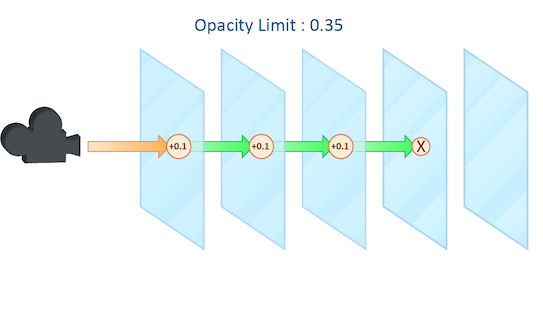
As a ray travels through many transparent surfaces, or through a volume, it will calculate the cumulative amount of Opacity. When this value exceeds the Opacity Limit mantra will assume all surfaces beyond this point are opaque.
This parameter behaves in a similar fashion to both the Reflect and Refract Limit but operates on accumulated values rather than simply the number of surfaces the ray has passed through.
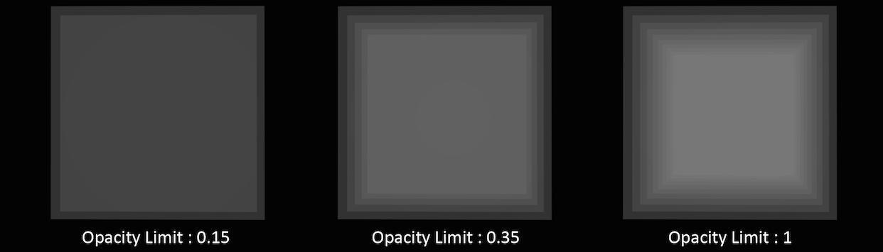
In this example, each grid has a shader attached with an opacity value of 0.1. It is important to remember that in this case “transparent” refers to objects whose opacity is less than 100% and does not include refractive objects which can appear transparent.
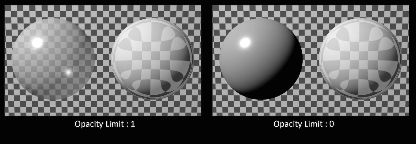
In this example, the sphere of the left has an opacity of 0.5, with no refraction. The sphere on the right has an Opacity of 1 with refraction enabled. You can see that the Opacity Limit has no effect on the amount of refraction, only affecting objects whose opacity value is less than 1.
While reducing the Opacity Limit may save a small amount of render time (1 – 5%) using low values may result in banding and other artifacts when your camera is moving or an animation is evolving. This can be especially noticeable in smoke simulations where opacity values are constantly changing.
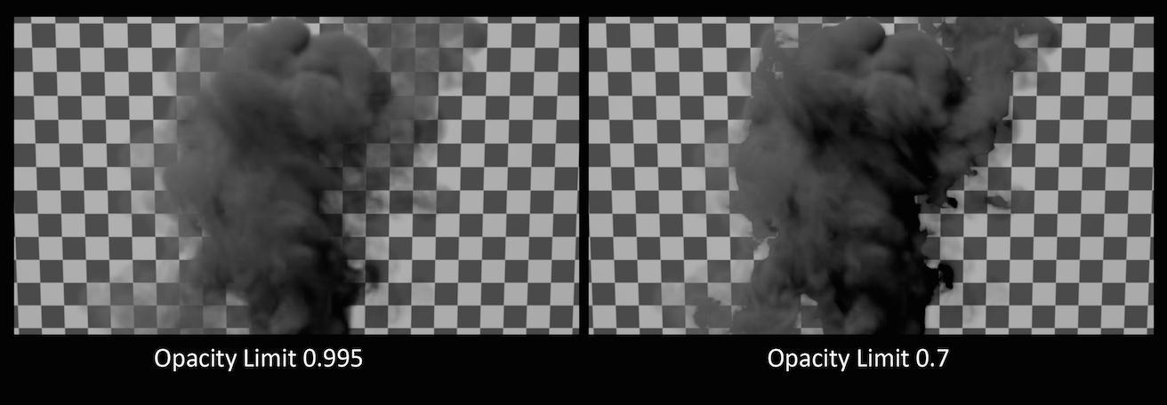
The default value for Opacity Limit is quite aggressive, changing this value should be done carefully and the results inspected across a range of frames in an animated sequence.
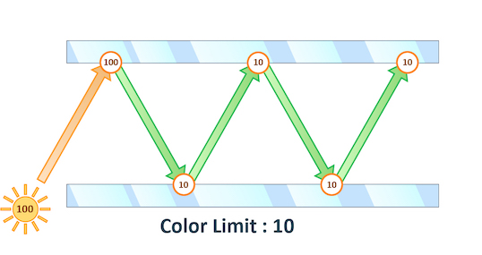
The maximum value a shading sample is allowed to return from indirect sources. When rendering using PBR the path’s total illumination is also constrained.
Physically Based Rendering can cause “spikes” in color values when extremely bright indirect light sources are under sampled. This results in “fireflies” in the final rendered image which can be very difficult to remove without very high sampling rates.
You can see in this example that even at 12×12 pixel samples, the “fireflies” still remain. Adjusting Min and Max indirect rays sample settings could remove this noise, but at the cost of longer render times.
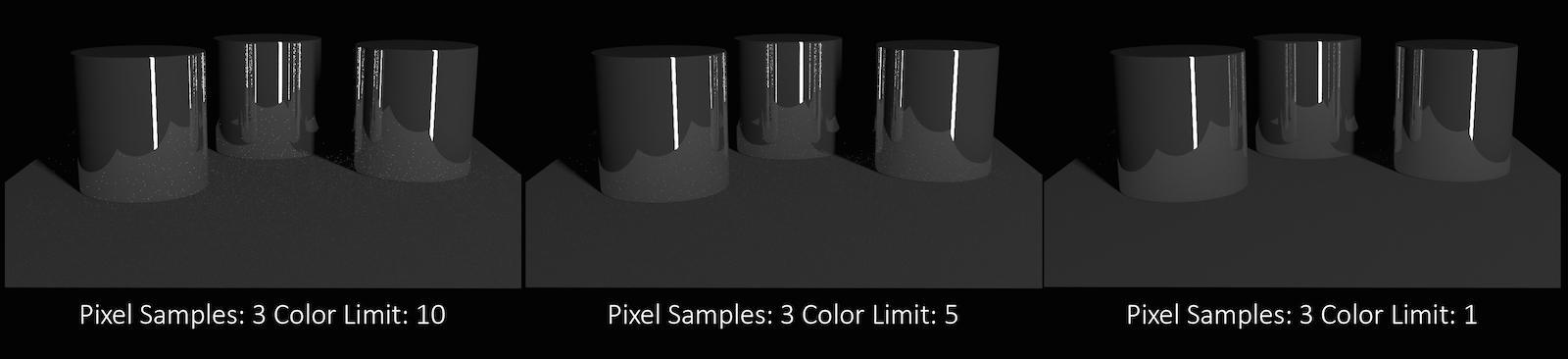
Decreasing the Color Limit parameter clamps the color values in these indirect samples and can help to avoid these “spikes”.
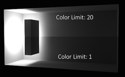
Reducing the color Limit can be an effective way of removing “fireflies” without increasing sampling rates. However, clamping the values in indirect lighting can result in an overall reduction in the amount of light in your scene. This is especially evident in scenes which are mostly illuminated by indirect light.
This parameter controls the path depth beyond which Color Limit clamping is applied.
To improve efficiency when shading transparent objects, mantra will queue a number of transparent surfaces before shading. This specifies the number of surfaces to queue. This can have a dramatic effect on volume rendering for example.
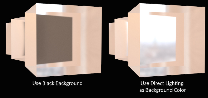
Controls how Mantra deals with rays that reach the ray tracing limit (For example the Reflect Limit or Refract Limit).
In this example, the refract Limit has been set to 2.
Setting At Ray Limit to Use Black Background will simply render black once the limits are reached. This is the default setting and will work in most scenes since the Reflect or Refract Limit is unlikely to be reached. However, in scenes where the limit is noticeable in the rendered image, the black color can be quite noticeable and stand out against the colors in the scene.
In this case, increase the limit until the effect is avoided or use the Use Direct Lighting as Background Color option. This will replace the black color with whichever color or image is used in your direct lighting, for instance an Environment Light.
For More Information about how the settings on an Environment Light affect this parameter see lighting.
When At Ray Limit is set to Use Direct Lighting as Background Color, direct lighting will be used for components in this list that have exceeded their limit. For example, if set to refract reflect only rays that have exceeded the refract/reflect limits would use direct lighting.
When At Ray Limit is set to Use Direct Lighting as Background Color this mask controls which lights contribute to direct lighting.
Note
This mask is intersected with lights affecting the material being shaded. Lights not found in both masks are ignored.
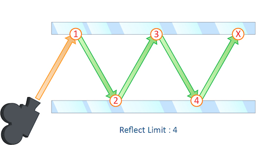
The number of times a ray can be reflected in your scene.
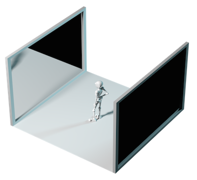
This example shows a classic “Hall of Mirrors” scenario with the subject placed between two mirrors.
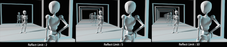
This effectively creates an infinite series of reflections.
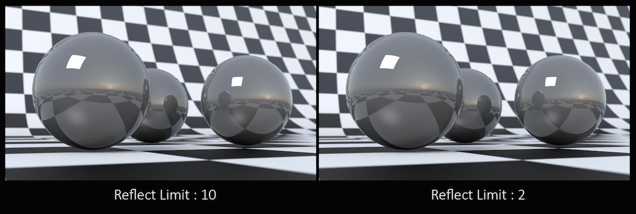
From this camera angle the reflection limits are very obvious and have a large impact on the accuracy of the final image. However, in most cases the reflection limit will be more subtle, allowing you to reduce the number of reflections in your scene and optimize the time it takes to render them.
Remember that the first time a light source is reflected in an object, it is considered a direct reflection. Therefore, even with Reflect Limit set to 0, you will still see specular reflections of light sources.
To control what happens when the maximum number of reflections is exceeded, use At Ray Limit.
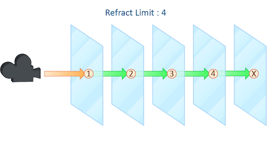
This parameter control the number of times a ray be refracted in your scene.
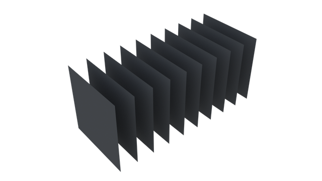
This example shows a simple scene with ten grids all in a row.
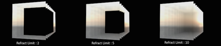
By applying a refractive shader, we will be able see through the grids to an image of a sunset in the background.
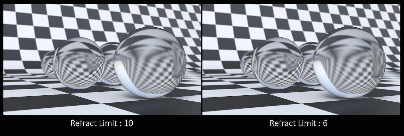
From this camera angle, in order for the image to be accurate, the refraction limit must match the number of grids that that are in the scene. However, most scenes will not have this number of refractive objects all in a row and so it is possible to reduce the refract limit without affecting the final image while also reducing the time it takes to render them.
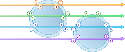
Keep in mind that this Refract Limit refers to the number of surfaces that the ray must travel through, not the number of objects.
Remember that the first time a light source is refracted through a surface, it is considered a direct refraction. Therefore, even with Refract Limit set to 0, you will see refractions of Light Sources. However, since most objects in your scene will have at least two surfaces between it and the light source, direct refractions are often not evident in your final render.
To control what happens when the maximum number of refraction is exceeded, use At Ray Limit.
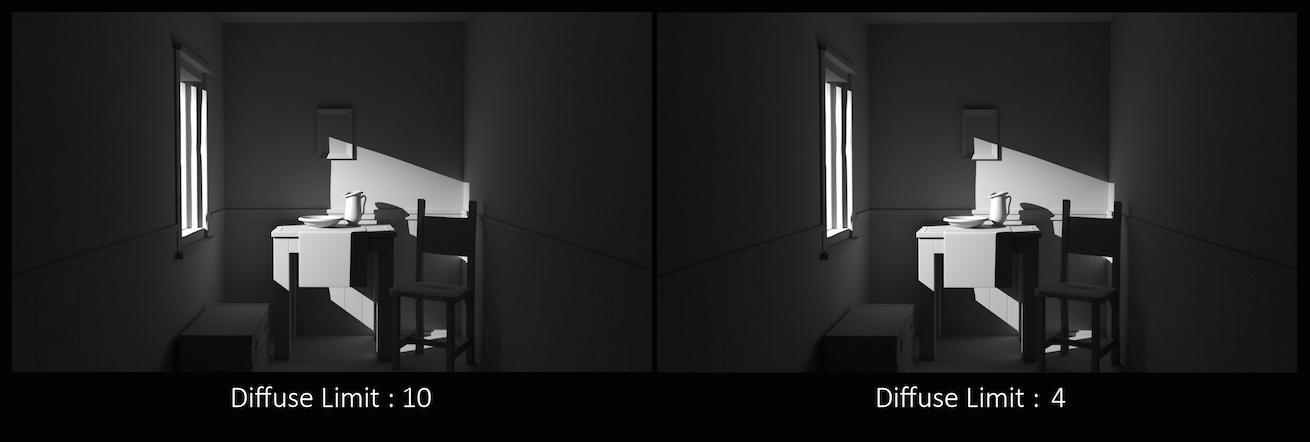
The number of times diffuse rays can propagate through your scene.
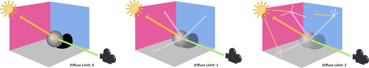
Unlike the Reflect and Refract Limits, this parameter will increase the overall amount of light in your scene and contribute to the majority of global illumination. With this parameter set above zero diffuse surfaces will accumulate light from other objects in addition to direct light sources.
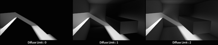
In this example, increasing the Diffuse Limit has a dramatic effect on the appearance of the final image. To replicate realistic lighting conditions, it is often necessary to increase the Diffuse Limit. However, since the amount of light contribution usually decreases with each diffuse bounce, increasing the Diffuse Limit beyond 4 does little to improve the visual fidelity of a scene. Additionally, increasing the Diffuse Limit can dramatically increase noise levels and render times.
The number of times a volumetric ray can propagate through a scene. It functions in a similar fashion to the Diffuse Limit parameter.
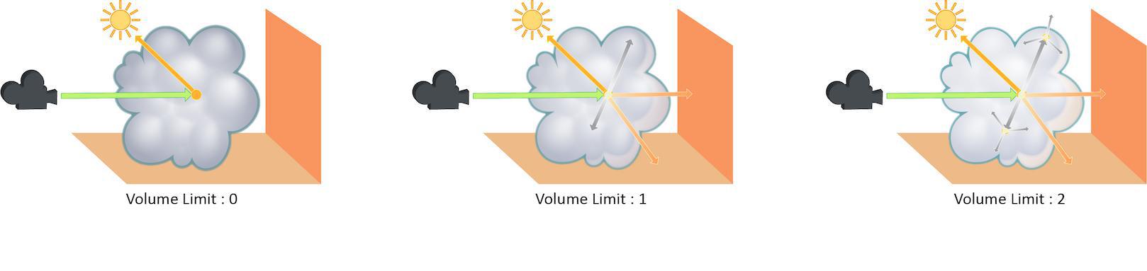
Increasing the Volume Limit parameter will result in much more realistic volumetric effects. This is especially noticeable in situations where only part of a volume is receiving direct lighting. Also, in order for a volumetric object to receive indirect light from other objects, the Volume Limit parameter must be set above 0.
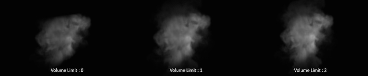
With the Volume Limit set to values above zero, the fog volume takes on the characteristic light scattering you would expect from light traveling through a volume. However, as with the Diffuse Limit, the light contribution generally decreases with each bounced ray and therefore using values above 4 does not necessarily result in a noticeably more realistic image.
Also, increasing the value of this parameter can dramatically increase the amount of time spent rendering volumetric images.
As rays propagate through the scene, they contribute less and less to the final color of the surface. When the contribution becomes less than the ray weight, no further rays will be sent. This is similar to the renderer:opacitylimit. vm_rayweight will not affect volume renders.
Enables random early cut off of ray paths when path tracing. This lets you increase overall path limits (i.e. the Diffuse Limit) while trading off a little stochastic noise for rendering efficiency.
Controls the method used to determine for early cut off of ray paths.
Probability
The chance for termination is determined by the Cut Off Threshold value.
Albedo
The albedo of the surface at each bounce is used as the probability to cut short ray paths. This means that darker surfaces will result in earlier cut off.
Throughput
The path’s combined throughput divided by the value of the Cut Off Threshold determines the probability.
This value affects the probability that ray paths will be cut short. Smaller values will cause paths to be cut off earlier (faster renders).
This parameter specifies the minimum number of bounces that occur before paths can be cut off.
Meta data 
A string containing a space-separated list of property values to save into the output .rat/.tbf file (such as a texture or deep shadow map). You can read the saved values out of a texture using the teximport VEX function in a shader.
The defaults save mostly camera- and image-related properties, but you can save the value of any mantra property, such as renderer:version.
The name of the image creator. By default uses the current user’s log in name.
Houdini, TIFF, PNG formats
By default, after rendering an EXR image, Mantra will post-process the image to set the data window, render time, and other metadata. Turn this off to prevent Mantra from adding metadata to EXR images.
After rendering an EXR image, Mantra will determine and record the rectangle of data whose values are above EXR Data Window Threshold in the image planes specified by EXR Data Window Planes, with an added padding of EXR Data Window Padding pixels on each side of the rectangle. This is equivalent to running the iautocrop program on the output image.
When Set EXR Data Window is on, the number of pixels to expand the computed data window on each side. This can give a bit of padding around the data window, if it is needed for filtering purposes in another application.
When Set EXR Data Window is on, include all pixels in any planes specified by EXR Data Window Planes whose values are strictly greater than this value. For example, if the value is 0 and only the A plane is selected, the data window rectangle will include all pixels with opacity greater than zero.
When Set EXR Data Window is on, include all pixels whose values are strictly greater than EXR Data Window Threshold in any of these image planes. This field supports wildcards and removals, like *, to specify all planes, or diffuse* ^diffuse3, to specify all planes whose names start with diffuse, except the diffuse3 plane.
Type of image compression to use in TIFF files. Possible values are "None", "LZW", "AdobeDeflate", "Deflate", "PackBits", "JPEG", "PixarLog", "SGILog", "SGILog24", "LZMA", "Zstd".
Parameter to TIFF compressor. Leave this set to “auto”. Possible values are "auto", "none", "horizontal".
Type of image compression to use in RAT (Houdini texture) files. Possible values are "deflate", "none".
Color space for Cineon format images. Possible values are "log" (unconverted), and "lin" (linear).
White point for Cineon format images, integer from 0 to 1023. The white-point of the image used during quantization. Normally you should leave this parameter at the default value of 1 unless you wish to darken or lighten the image.
Compression type for EXR format images. Possible values are "none", "rle", "zips", "zip", "piz", "pix", "b44", "b44a", "dwaa", "dwab".
Sets the amount of compression to use with OpenEXR’s DWAA or DWAB compression type. Higher values result in better compression and faster reads, but lower quality.
Additional attributes to set on EXR format images. The string is interpreted as
a Python dictionary, such as {'int_attr':1, 'flt_attr':2.3, 'vec3_attr':(0,1,2), 'str_attr':'foo'}.
Any values that cannot be parsed or isn’t recognized, will be silently ignored. The set of Python
value types recognized for use as an EXR attributes are: bool, int, float, string, and
3-, 4-, 9-, 16-value tuple and list of float. Due to lack of 4-value vector attributes in the
EXR format, the Box type attribute is used instead.
Note
The standard attributes cannot be overridden by this attribute string.
How to interpret mantra’s framebuffer when saving out PNG. Possible values are "premult" or "unpremult".
Note
Mantra’s framebuffer always stores colors premultiplied by alpha, whereas PNG expects unpremultiplied colors, so using the default setting of "premult", it will correctly interpret the data and predivide RGB channels upon write. If set to "unpremult", then it will assume that the alpha is unassociated and will not touch RGB channels.
The "unpremult" option may be used for storing certain effects losslessly (such as emission that’s not tied to opacity and thus does not contribute to alpha), however keep in mind that it will be outside the PNG specification and will be interpreted incorrectly without user intervention.
Controls how MPlay deals with new frames. Possible values are "current" (add rendered frames to MPlay’s current sequence) or "new" (have MPlay start a new sequence).
Controls how MPlay inserts new frames into the current sequence. Possible values are "append" (add new frames on to the end of the current sequence), or "match" (replace frames with the same number in the current sequence).
When rendering to MPlay, all Houdini sessions will send the output to the same MPlay flipbook. This can be problematic when running multiple Houdini sessions. The MPlay Label lets you specify a label for the MPlay associated with the output driver. Only renders which match the given label will be sent to that MPlay.
Houdini Process ID
Uses the operating system process identifier so that the MPlay flipbook will only accept renders from that Houdini session.
HIP Name
Uses the $HIPNAME variable so the MPlay will only accept renders from the running $HIP file.
Output Driver Name
The MPlay flipbook will only accept renders from the given output driver. For example, if you copy paste the output driver, each output driver will be sent to different MPlay flipbooks because the operators will have different names.
If there are multiple Houdini sessions, there may be output drivers in the other session which match the same operator name.
For example, say you have two output drivers: “High quality” and “Low Quality”. If you set the MPlay Label to different values for the two output drivers, each render will be sent to different MPlay sessions.
The direction in which MPlay renders the image. Possible values are "middle" (middle out), "top" (top down), or "bottom" (bottom up).
Objects 
Output 
The image or device where the resulting image will be rendered. You can set this value to ip which renders the image in MPlay, or you can save it to an image. The following image types are supported: .pic, .tif, .sgi, .pic.gz, .rat, .jpg, .cin, .rta, .bmp, .tga, .rad, .exr, and .png.
Include $F in the file name to insert the frame number. This is necessary when rendering animation. See expressions in file names for more information.
The image format or device for the output image. If you leave this at the default value of Infer from filename, the image format will be selected based on the file extension (eg. .pic will automatically generate a Houdini format image.)
Determine how the output driver should deal with existing rendered frames.
no
Overwrite any existing files.
exist:vm_picture
Skip rendering when a disk file already exists.
valid:vm_picture
Skip rendering only when the disk file that exists is a valid image file.
This parameter checks only the main image, not any deep raster or secondary images.
Controls how transparent samples are combined to produce the color values for individual pixel samples. The sample filter is used to composite transparent surfaces before the pixel filter produces final pixel colors.
Opacity Filtering (alpha)
Uses the opacity (Of) values for transparent samples for compositing. This option should be used whenever correct transparent compositing is required. For example, when rendering volumes, sprites, or transparency.
Full Opacity Filtering (fullopacity):
When stochastic transparency is enabled, this option causes a channel to be evaluated and composited with every opacity evaluation - as opposed to only being composited with the samples that are selected for full shading. It can be used to produce smoother results for channels that are fast to evaluate such as Ce or direct_emission. When stochastic transparency is disabled, this option behaves the same way as Opacity Filtering.
Closest Surface (closest)
Ignores the opacity values and just copies the color for the closest transparent sample into the image. This option disables transparency for a given deep raster plane and will only produce the closest sample results.
Specifies the pixel filter used to combine sub-pixel samples to generate the value for the single pixel. The filter is normally specified as a filter type (eg. gauss) followed by an x and y filter width in pixels. To blur the image, increase the filter width.
There are several different pixel filters available.
minmax ‹style›
The style may be one of:
-
min– Choose the value of the sample with the smallest z value (closest to camera). -
max– Choose the value of the sample with the maximum z value (farthest from camera). -
median– Choose the value of the sample that has the median z value of all samples. -
edge– Filter using a unit box but only averages samples with object coverage. This filter will have the effect of disabling external edge antialiasing. -
ocover– First, choose the object which covers most of the pixel, then take the average value from the sub-pixels of that object only. This filter is similar toedgebut it also disables internal edge antialiasing between object boundaries. -
idcover– First, choose the object which covers most of the pixel, then select a single sample from that object for the pixel value. This filter is similar toocoverbut it will not average any samples. Use this filter mode for planes that will be interpreted as integers, such as object or primitive identifiers. The sample chosen will be unordered. -
omin– First, choose the object which covers most of the pixel, then choose a single sample from that object for the pixel value. Chooses the sample with the smallest z value (closest to camera). -
omax– First, choose the object which covers most of the pixel, then choose a single sample from that object for the pixel value. Chooses the sample with the maximum z value (farthest). -
omedian– First, choose the object which covers most of the pixel, then choose a single sample from that object for the pixel value. Chooses the sample with the median z value.
point
Choose the sub-pixel closest to the center of the pixel.
box [‹width› ‹height›]
Use a box filter to combine the sub-pixels with a filter size given by width/height.
gaussian [‹width› ‹height›]
Use a Gaussian filter to combine the sub-pixels with a filter size given by width/height.
bartlett [‹width› ‹height›]
Use a Bartlett (cone) filter to combine the sub-pixels with a size width given by width/height.
blackman [‹width› ‹height›]
Use a Blackman filter to combine the sub-pixels with a filter size given by width/height.
catrom [‹width› ‹height›]
Use a Catmull-Rom filter to combine the sub-pixels with a size width given by width/height.
hanning [‹width› ‹height›]
Use a Hanning filter to combine the sub-pixels with a filter size given by width/height.
mitchell [‹width› ‹height›]
Use a Mitchell filter to combine the sub-pixels with a filter size given by width/height.
sinc [‹width› ‹height›]
Use a sinc filter to combine the sub-pixels with a filter size given by width/height.
edgedetect
Use an edge detection filter to find edges based on z-depth, object boundaries, and color gradients.
combine -t ‹tolerance›
Use a Ray Histogram Fusion-based filter to combine the sub-pixels with the given similarity tolerance.
Note
This option is very slow and may eliminate some noise in an image, even if the noise is supposed to be there (ie, not just noise due to undersampling), resulting in loss of detail.
denoise optix [-a ‹AOV›]
The storage type for the main image. The type of quantization used will affect image quality and size. If you need to adjust the image’s dynamic range in compositing, you should normally leave this value at the default of 16-bit floating point.
The default is "float16" for the first plane, and "float" for secondary planes. You can override the first plane’s value with the -b command line argument to mantra.
Normally the image resolution is set on the camera object. Turn this on to enable controls that modify or override the camera’s settings.
When Override camera resolution is on and Resolution scale is “User specified resolution”, lets you set the resolution of the output image, overriding the settings on the camera.
When Override camera resolution is on, allows you to scale whatever resolution is set on the camera. To completely override the camera’s resolution, choose “User specified resolution”.
The pixel aspect ratio represents the width of a pixel divided by the height of a pixel. It is not the aspect ratio of the image (which is determined by the resolution of the image). This parameter does not affect rendering, it is only used to change how images are displayed, by stretching the pixels by this factor.
When you render a target node with this option on using HQueue, the server will split frames to render into separate tiles and render each tile as a separate job. When you render locally with this option on, Mantra will render a single tile instead of the entire frame.
Tiled render can also be enabled using -t command line option to mantra, which can be used to render a tile locally without having to generate an IFD for each tile with Tiled render enabled.
Which tile to render, when rendering locally with Tile render on. Tile numbers start at 0 in the top left and increase left to right, top to bottom.
When enabled, image tile data will be frequently written out to a checkpoint file in the same directory as the output file. If the process is terminated before completing the render, it can then be resumed by turning on Resume from Checkpoint Files and restarting. To specify an alternative checkpoint file name, enable __Checkpoint File Name___.
Warning
Checkpointing does not work when creating a deep shadow map or deep camera map.
The checkpoint file will be deleted if the render completes successfully.
When enabled, before rendering, Mantra will look for a checkpoint file corresponding with the current output file, generated by a previous partial render that had Output Checkpoint Files enabled. If possible, Mantra will only render areas that are needed for remaining regions of the output image. To specify an alternative checkpoint file name, enable __Checkpoint File Name___.
If both Output Checkpoint Files and Resume from Checkpoint Files are enabled and a valid checkpoint file is loaded, any additional image tile data rendered will be appended to the checkpoint file.
When enabled, checkpoint files used by Output Checkpoint Files and Resume from Checkpoint Files will be named based on Checkpoint File Name.
When Override Checkpoint File Name is enabled, this specifies the names for checkpoint files used by Output Checkpoint Files and Resume from Checkpoint Files. It can contain expressions.
When the amount of data queued to write to a checkpoint file reaches this many megabytes, the data will be flushed to the checkpoint file, even if it has been less than Checkpoint Period seconds since the last write.
When a render tile completes and it has been at least this many seconds since the last write to the checkpoint file, the data will be flushed to the checkpoint file, even if it is less than Checkpoint Cache Size megabytes of data.
Normally, sub-pixel samples are filtered using the pixel filter defined on an image plane. When this is turned on, each sub-pixel is output without any pixel filtering performed.
The image:resolution property will be scaled by the image:samples property to determine the actual output image resolution. For example, if image:resolution was (1024,512) and image:samples was (4,6), the image rendered would have a resolution of 4096 by 3072. Each pixel would represent a single unfiltered sub-pixel sample.
Create image from viewing camera
Renders an image from the viewing camera. Sometimes, it is useful to skip this render, for example, when rendering shadow maps.
Enable or disable shadow map generation. Each light also has its own controls to determine whether shadow maps will be generated.
PBR 
The shader used to evaluate samples for the PBR rendering engine. If no shader is specified, the default VEX Pathtracer shader is used. Normally you should not need to assign a shader for this parameter unless you are a shader writer and need to make adjustments to the PBR shading algorithm.
Photon 
Add this property to control the minimum photon acceptance ratio. This parameter is a value between 0 and 1 to control the minimum proportion of photons sent that must be stored before mantra will bail out on photon generation from that light.
When renderer:renderengine is “photon”, this determines the photon map file for diffuse photons (irradiance).
When renderer:renderengine is “photon”, this determines the photon map file for caustic photons (specular bounces).
When sending photons from this light source, this is the category expression to determine which objects will receive photons.
Controls the proportion of photons that should be generated by this light relative to other lights in the scene. By default, all lights have an equal weight of 1.
Affects the way that photons are traced through the scene. When a photon hits a surface the parameter affects it depending on the selected option. This is only used if the scene has a light (such as the GI Light) that uses photon mapping.
None
Photon is not modified, bouncing as usual (this is the default).
Pass Through
Photon passes through the surface, not being stored.
Block
Photon is stopped, ending the path trace for that photon.
Preview 
Preview uses fixed samples per pass
Base the number of samples per pass on vm_iprpasssamples. Primarily useful for performance testing.
Sets the number of samples taken per pass, as a multiple of the minimum number of samples per pass. Primarily useful for performance testing.
Only used for performance testing. A fake relighting buffer is created and zeroed.
Render 
The size (in pixels) of the tiles rendered by mantra. Larger tile sizes may consume more memory.
Color Tile Borders by Thread Index
Set the color of the tile borders to indicate which thread was responsible for rendering it. This can be be used to visually check for thread balancing issues.
This property will be used to cull out parts of the volume behind fully opaque portions. After shading of a surface, if the Of variable is less than this threshold, mantra will consider that the surface doesn’t exist and samples will be ignored.
Whether to use a fixed size cache (vm_cachesize) or whether to use a proportion of physical memory (vm_cacheratio)
The proportion of physical memory Mantra will use for its unified cache.
For example, with the default vm_cacheratio of 0.25 and 16 Gb of physical memory, Mantra will use 4 Gb for its unified cache.
The unified cache stores dynamic, unloadable data used by the render including the following:
-
2D
.rattexture tiles -
3D
.i3dtexture tiles -
3D
.pcpoint cloud pages (when not preloaded into memory) -
Tessellated meshes required by ray tracing:
-
Displacements
-
Subdivision surfaces
-
Bezier and NURBS primitives
-
An explicit memory limit for the unified shading cache. This is deprecated in favor of using the Cache Memory Ratio.
Perform hidden surface removal. When hidden surface removal is disabled, all surfaces in the camera’s frustum will be rendered, regardless of whether they are occluded. This can impact render time significantly.
When enabled, automatically set the thread count (renderer:threadcount IFD property) to the number of CPUs of the rendering machine.
When Use Max Processors (renderer:usemaxthreads IFD property) is disabled, sets the number of threads Mantra uses for rendering.
Controls what value is set for $HIP in the IFD file. By default this is the same as $HIP in Houdini, which is usually what you want. However, you may need to set $HIP to something different in the IFD if you are doing interesting things with a render farm, for example.
Controls which style sheets defined in the hip file are embedded into the IFD. Standard Houdini pattern matching is used on each embedded style sheet name.
Specifies which style sheets mantra should apply during rendering. This is a space separated list of either names of style sheets embedded in the hip file, or external JSON files on disk. As with individual styles within a single style sheet, style sheets later in the list take precedence over style sheets earlier in the list.
Enabling this option forces all node bundles to be saved to the IFD. Bundles can be used by style sheets to target objects. If this feature is used in style sheets defined on disk, you may need to enable this option to get the expected results from the style sheets.
Controls which SHOPs are embedded in the generated IFD. This parameter can be used to force all SHOPs or all Material SHOPs to be embedded even if Houdini does not find explicit references to those SHOPs on the output objects and geometry.
Enabling this checkbox will expand any variables in OTL paths, breaking the dependency on Houdini environment variables, but possibly making the IFD less portable.
Mantra is able to load the shader directly from the OTL when Houdini uses a shader defined in an OTL. When shaders are built using VOPs, the shader must be embedded in the IFD. Enabling this option will force Houdini to embed the shaders defined by OTLs.
This option makes the IFD more self-contained so that machines which don’t have the OTL installed (or a different version of the OTL) are able to evaluate the shaders correctly.
However, if you have complicated shaders, embedding them will bloat the size of the IFD significantly.
Whether to allow ray-tracing. By disallowing ray-tracing no ray-traced shadows, reflections, refractions, etc. will be performed.
Whether to enable the irradiance and occlusion VEX functions. This also controls whether irradiance caching will be enabled.
Whether to enable dicing of displacements/subdivisions. Disabling this setting will have the same effect as disabling Polygons as subdivision on all objects and disabling true displacements on all materials.
Allow interruption of rendering. This is typically enabled for IPR rendering.
Controls the type of ray tracing accelerator used by mantra. A ray tracing accelerator is a spatial data structure used to optimize the performance of ray intersection tests against complex geometry.
KD-Tree ("kdtree")
Ray trace using a KD-Tree. Normally, the KD-Tree will produce the fastest raytracing performance at a modest initialization time. It is possible to control the performance/quality tradeoff for KD-Tree construction with the KD-Tree Memory Factor parameter (vm_kdmemfactor).
Bounding Volume Hierarchy ("bboxtree")
Ray trace using a bounding volume hierarchy. Sometimes a bounding volume hierarchy will be faster to construct and/or faster to raytrace than a KD-Tree.
Change the memory/performance tradeoff used when constructing KD-Tree acceleration data structures. Values larger than 1 will cause mantra to use proportionally more memory and take longer to optimize the tree in an attempt to make ray tracing faster. Smaller values will cause mantra to use proportionally less memory and take less time to optimize the tree, while possibly compromising ray tracing performance. The default value of 1 will try to balance the amount of memory used by ray tracing data structures with the amount of memory used by geometry.
If you are noticing long tree construction times, try decreasing the KD memory factor to 0.1. If your render is too slow after tree construction, increase the value until you find a good balance of tree construction time vs. render performance.
Enable Oriented BVH Construction
Enables a ray tracing tree construction algorithm that uses rotations to locally align the axes with the dominant geometric directions. This approach only works on curves, and will usually increase the amount of time required to build the ray tracing tree. However the resulting trees may improve ray tracing performance particularly for bundles of long curves that are not aligned to the x, y, or z axis as can commonly occur when rendering long hair.
The number of curve segments to group together when building ray tracing objects for curves. Larger values will reduce memory use but will decrease performance since the ray tracer needs to attempt more ray intersections. A value of 1 will create one ray tracing object per curve segment resulting in the best possible ray tracing performance but can increase memory use substantially.
Specifies the amount of time to render in seconds, or 0 to render until completion.
By default, mantra lets the system perform a cleanup of the process resources. A quick-exit is very efficient, but this case, mantra won’t do any cleanup itself. This means that custom VEX cleanup functions may not be run.
When true, the object will not be rendered by primary rays. Only secondary rays will hit the object.
(See the Render Visibility property).
If this option is turned off, then the instance will not be rendered. The object’s properties can still be queried from within VEX, but no geometry will be rendered. This is roughly equivalent to turning the object into a transform space object (the object would only be available as a transform for VEX functions, but have no geometry).
See Render Visibility (vm_rendervisibility property).
Controls the visibility of an object to different types of rays using a category expression. This parameter generalizes the Phantom and Renderable toggles and allows more specific control over the visibility of an object to the different ray types supported by mantra and VEX.
-
“primary” - Rays sent from the camera
-
“shadow” - Shadow rays
-
“diffuse” - Diffuse rays
-
“reflect” - Reflections
-
“refract” - Refractions
For example, to create a phantom object, set the expression to “-primary”. To create an unrenderable object, set the expression to the empty string “”. These tokens correspond to the string given to “raystyle” in the VEX trace() and gather() functions.
This is set to the “root” of the object tree. In Houdini, this is typically /obj. If object names are specified using relative paths (i.e. light1 or subnet1/light1), this is used to determine the full path. This will be deprecated in the future in favor of category selection.
Polygons as subdivision (Mantra)
Render polygons as a subdivision surface. The creaseweight attribute is used to perform linear creasing. This attribute may appear on points, vertices or primitives.
When rendering using OpenSubdiv, in addition to the creaseweight, cornerwieght attributes and the subdivision_hole group, additional attributes are scanned to control the behaviour of refinement. These override any other settings:
-
int osd_scheme,string osd_scheme: Specifies the scheme for OSD subdivision (0 or “catmull-clark”; 1 or “loop”; 2 or “bilinear”). Note that for Loop subdivision, the geometry can only contain triangles. -
int osd_vtxboundaryinterpolation: The Vertex Boundary Interpolation method (seevm_osd_vtxinterpfor further details) -
int osd_fvarlinearinterpolation: The Face-Varying Linear Interpolation method (seevm_osd_fvarinterpfor further details) -
int osd_creasingmethod: Specify the creasing method, 0 for Catmull-Clark, 1 for Chaikin -
int osd_trianglesubdiv: Specifies the triangle weighting algorithm, 0 for Catmull-Clark weights, 1 for “smooth triangle” weights.
The algorithm used to render subdivision surfaces. Currently, this can be either mantra_catclark or osd_catclark.
A primitive group of polygons which should be rendered as a subdivision surface. This is only effective if vm_rendersubd is enabled.
Note
This is a group on the final geometry that is being rendered. For example, if the top-level primitive is an Alembic primitive, then the vm_subdgroup refers to a given face set in that primitive.
The dicing quality when rendering subdivision surfaces as osd_catclark. This value is multiplied by the shading quality and shading factor to determine the number of refinement levels for the surface.
OpenSubdiv Vertex Boundary Interpolation
How subdivision vertex (Houdini point) attributes are interpolated on boundaries.
-
0: Do not interpolate boundaries
-
1: Sharpen edges
-
2: Sharpen edges and corners
OpenSubdiv FVar Linear Interpolation
How subdivision face varying (Houdini vertex) attributes are interpolated.
-
0: Smooth everywhere (“edge only”)
-
1: Sharpen corners only
-
2: Sharpen edges and corners
-
3: Sharpen edges and corners and propagate corners
-
4: Sharpen all boundaries (“always sharp”)
-
5: Bilinear interpolation
Rendering 
Mantra will render with depth of field. The parameters controlling depth of field may be found on the camera object.
This is the “master switch” for simulated motion blur when rendering. Turning it on enables transformation motion blur (blurring by interpolating each object’s transforms between frames). You can set the number of transform blur samples using xform_motionsamples. To enable deformation motion blur, increase geo_motionsamples.
See motion blur for more information about rendering motion blur.
This is an advanced property which can be added per object.
If the property is set, SOHO will automatically enable the Engine Procedural for this object. The object network itself will be saved as an HDA in the IFD stream for use by the Engine Procedural. At render time, mantra will take the geometry generated by the Display SOP and instance it to each point in the geometry on the Render SOP’s geometry. For each instance, point attributes on the Render SOP’s points that match parameters on the object network will be applied, allowing for geometry variation at render time.
Mantra has three different levels of support for the engine procedural.
These modes are set using the -e command line option (or the
MANTRA_ENGINE_PROCEDURAL environment variable):
-
none: In this mode, mantra can bypass setting up an environment to evaluate SOP networks. This can improve start-up time for mantra. In most cases, this is an insignificant amount of time. -
basic: Allows generation of point and curve geometry. -
full: Allows generation of any types of geometry. This option will make mantra use an Engine license instead of a Render license.
Note
The engine procedural will try to set a parameter named cooking_in_engine to 1 when the HDA is being evaluated in mantra. This allows the SOP network to cook differently for display in Houdini and rendering in Mantra.
Engine Procedural - Unload SOP Geometry
When the Auto Engine Procedural is set, this property will tell mantra
whether to unload the SOP geometry after cooking. Unloading SOP geometry
will free up memory in mantra, but may cause some SOP/Object networks to
perform additional computation.
Engine Procedural - HDA Uses LOD Parameter
When the Auto Engine Procedural is set, this property will tell mantra
whether to compute the bounding box LOD and set a lod parameter the HDA.
This allows the SOP network to generate different geometry based on the
level of detail in mantra.
When the LOD is not required, mantra can share geometry between instances
that have the same render parameters (similar to Cache Stamping Geometry
parameter on the Copy Stamp SOP). If the LOD is required, mantra can not
perform any sharing of geometry.
Engine Procedural - Orient HDA instances to points
When the Auto Engine Procedural is set, this property controls whether
the instanced geometry should be rotated based on the point attributes.
Each instance will always be translated to the instance point, but this
parameter controls whether attributes like pscale and N will be applied
to the instance transform.
Engine Procedural - Bounding Box SOP
When the Auto Engine Procedural is set, the SOP specified by this
property is used to determine the bounds of the generated hair at rendertime.
If not specified or empty the SOP with the display flag is used.
Tip
Rendering with motion blur can invalidate the cache of the SOP being cooked, causing all dependent nodes to recook when they are displayed in Houdini after a render. To avoid this, create a separate SOP for computing geometry to represent the bounding box of the display geometry. Use this property to specify the final node of that chain.
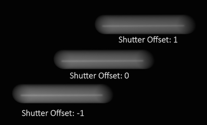
This parameter controls which segment of time will be considered when generating motion blur. A value of 1 will use the current position of the object and the position of the object on the next frame as the time interval to use for motion blur. A value of -1 will use the position of the object on the previous frame and the current position of the object as the time. A value of 0 will generate an interval which lasts halfway through the previous frame and half way into the next frame.
Adjusting this parameter is usually unnecessary unless you are attempting to match motion- blur which has been generated outside of Mantra (for example a photographic background plate).
Controls where the blur occurs in the image relative to the position of the object at the current frame. A value of -1 blurs from the position at the previous frame to the position in the current frame. A value of 0 blurs from halfway to the previous frame to halfway to the next frame. A value of 1 blurs from the current position to the position at the next frame. You can use fractional frame values and values greater than -1 or 1 to move the blur less or more.
To change the size of the blur, change the Shutter time (shutter property).
This parameter replaces the old Motion blur style (motionstyle) parameter, which only allows values of “before” (shutter offset=-1), “center” (shutter offset=0), and “after” (shutter offset=1).
The number of samples to compute when rendering transformation motion blur over the shutter open time. The default is 2 samples (at the start and end of the shutter time), giving one blurred segment.
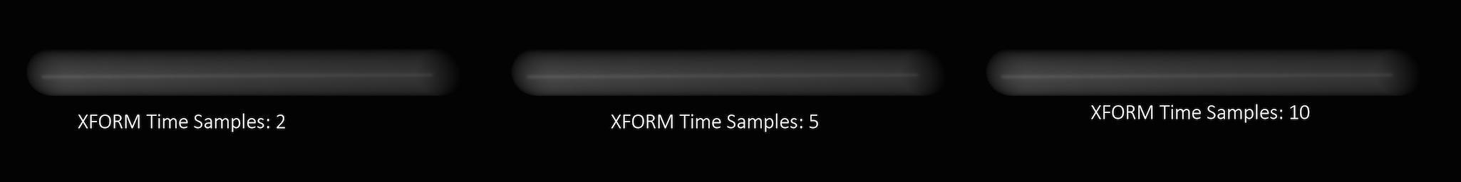
If you have object moving and changing direction extremely quickly, you might want to increase the number of samples to capture the sub-frame direction changes.
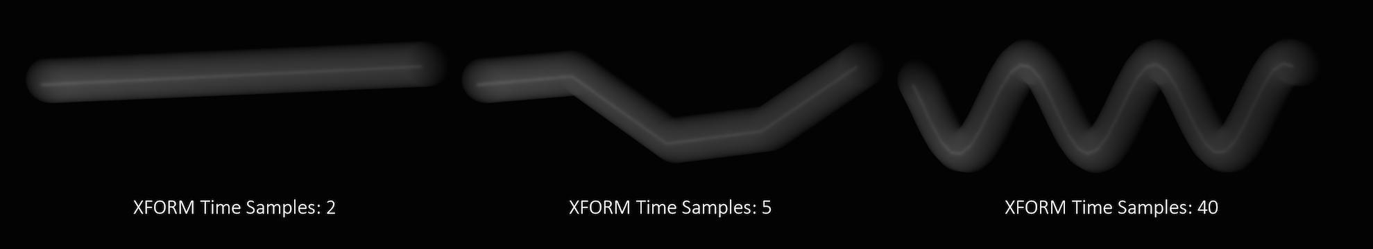
In the above example, it requires 40 transformation samples to correctly render the complex motion that occurs within one frame. (This amount of change within a single frame is very unusual and only used as a demonstration.)
Transformation blur simulates blur by interpolating each object’s transformation between frames, so it’s cheap to compute but does not capture surface deformation. To enable blurring deforming geometry, increase geo_motionsamples.
The number of sub-frame samples to compute when rendering deformation motion blur over the shutter open time. The default is 1 (sample only at the start of the shutter time), giving no deformation blur by default. If you want rapidly deforming geometry to blur properly, you must increase this value to 2 or more. Increasing the number of geometry time samples is relatively expensive because Houdini must cook the sub-frame geometry and send it to Mantra.
“Deformation” may refer to simple transformations at the Geometry (SOP) level, or actual surface deformation, such as a character or object which changes shape rapidly over the course of a frame.
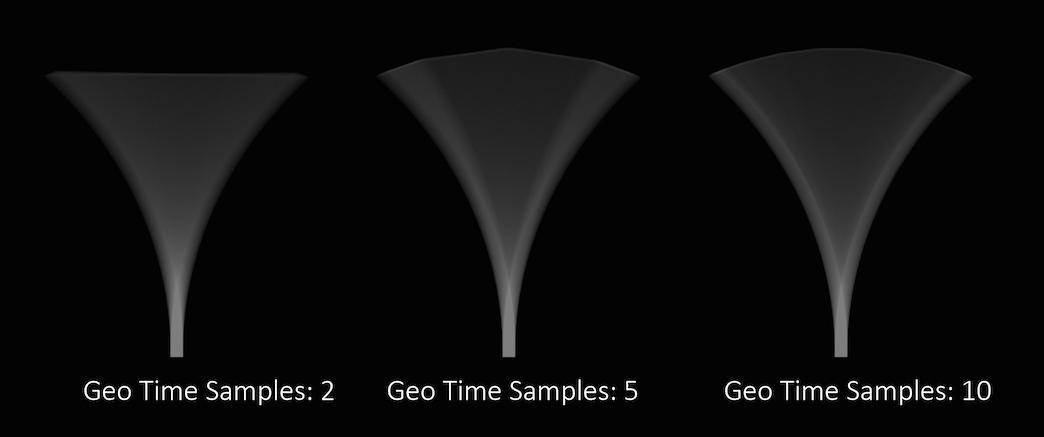
Objects whose deformations are quite complex within a single frame will require a higher number of Geo Time Samples.
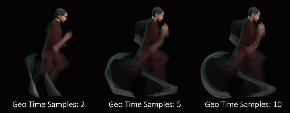
Deformation blur also lets you blur attribute change over the shutter time. For example, if point colors are changing rapidly as the object moves, you can blur the Cd attribute. You must explicitly specify which attributes to blur using the vm_segmentattrs property.
Increasing the number of Geo Time Samples can have an impact on the amount of memory Mantra uses. For each additional Sample, Mantra must retain a copy of the geometry in memory while it samples across the shutter time. When optimizing your renders, it is a good idea to find the minimum number of Geo Time Samples necessary to create a smooth motion trail.
Deformation blur is ignored for objects that have Velocity motion blur turned on.
See understanding mantra rendering for more information.
Micropolygon Rendering
Each primitive is diced up into micropolygons which are shaded and sampled independently.
Ray Tracing
The scene is sampled by sending rays from the camera. Each surface hit by a ray will trigger a surface shader execution.
Micropolygon Physically Based Rendering
Sampling is performed on micropolygons; however, all shading and illumination is performed using physically based rendering.
The number of rays used to compute shading is determined by the maximum ray-samples.
Physically Based Rendering
Sampling of the scene is performed using ray-tracing and shading is computed using physically based rendering.
In this case, the pixel samples determine the shading quality of the PBR engine.
Photon Map Generation
Rather than rendering an image, a photon map will be generated by sending photons from light sources into the scene. The photon map file to be generated is specified on the PBR tab.
Though this IFD token has an integer value, it’s also possible to set the value through a string value.
micropoly
Micropolygon scanline rendering (default).
raytrace
All rendering will be performed using ray-tracing.
pbrmicropoly
Physically Based Rendering using micro-polygon scanline rendering.
pbrraytrace
Physically Based Rendering using ray-tracing only.
photon
Photon map generation.
Sampling 
The lens focal distance and distance from the camera at which objects will be in focus. This is only used when rendering using depth of field. Objects outside this distance will be blurred.
Lens fstop. This is only used when rendering using depth of field. Determines blurriness of depth of field effects.
The shutter time refers to the portion of a frame the shutter is actually open. On a physical camera, this if often referred to as Shutter Speed. The renderer uses this determine motion blur. The value should be in the range [0,1].
A value of 0 for the shutter time would mean that there is no motion blur at all, as the shutter is only “Open” for an instant. A value of 1 on the other hand would mean that the shutter is open for the entire length of the frame.
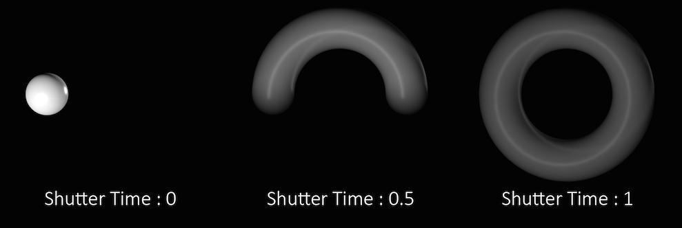
In the above example the sphere is rotating a full 360 degrees over the course of a single frame. You can see how the length of the “motion trail” or “blur” changes based on the shutter time. In most cases, the default value of .5 is appropriate for animated sequences and a good match for real world settings.
Keep in mind that this parameter controls the amount of time within a single frame, that the shutter is open. It does not refer to how long an individual frame is. To adjust the frame rate, change the Frames per Second parameter in the Global Animation Options.
Controls the opening of the shutter along shutter time through a grayscale ramp. The higher the ramp value at a given time point, the more time sample will be focused in that area. NOTE
The ramp is always evaluated across the entire range, regardless of the shutter time setting.
This menu lets you choose what type of geometry velocity blur to do on an object, if any. Separate from transform blur and deformation blur, you can render motion blur based on point movement, using attributes stored on the points that record change over time. You should use this type of blur if the number points in the geometry changes over time (for example, a particle simulation where points are born and die).
If your geometry changes topology frame-to-frame, Mantra will not be able to interpolate the geometry to correctly calculate Motion Blur. In these cases, motion blur can use a v and/or accel attribute which is consistent even while the underlying geometry is changing. The surface of a fluid simulation is a good example of this. In this case, and other types of simulation data, the solvers will automatically create the velocity attribute.
No Velocity Blur
Do not render motion blur on this object, even if the renderer is set to allow motion blur.
Velocity Blur
To use velocity blur, you must compute and store point velocities in a point attribute v. The renderer uses this attribute, if it exists, to render velocity motion blur (assuming the renderer is set to allow motion blur). The v attribute may be created automatically by simulation nodes (such as particle DOPs), or you can compute and add it using the ![]() Point velocity SOP.
Point velocity SOP.
The v attribute value is measured in Houdini units per second.
Acceleration Blur
To use acceleration blur, you must compute and store point acceleration in a point attribute accel (you can change the acceleration attribute name using the geo_accelattribute property). The renderer uses this attribute, if it exists, to render multi-segment acceleration motion blur (assuming the renderer is set to allow motion blur). The accel attribute may be created automatically by simulation nodes, or you can compute and add it using the ![]() Point velocity SOP.
Point velocity SOP.
When Acceleration Blur is on, if the geometry has a angular velocity attribute (w), rapid rotation will also be blurred. This should be a vector attribute, where the components represent rotation speeds in radians per second around X, Y, and Z.
When this is set to “Velocity Blur” or “Acceleration Blur”, deformation blur is not applied to the object. When this is set to “Acceleration Blur”, you can use the geo_motionsamples property to set the number of acceleration samples.
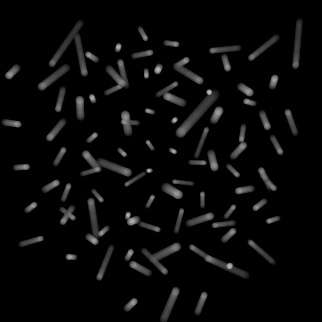
v) to do linear motion blur.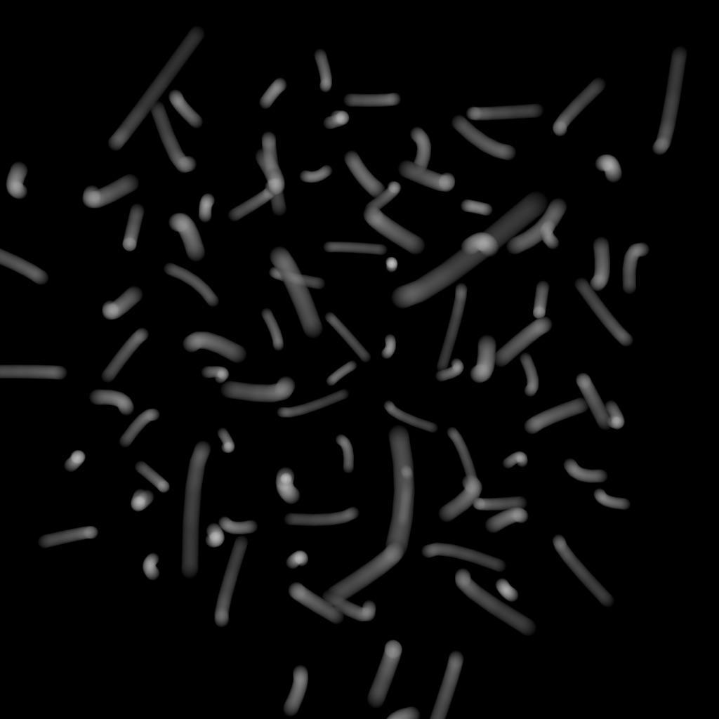
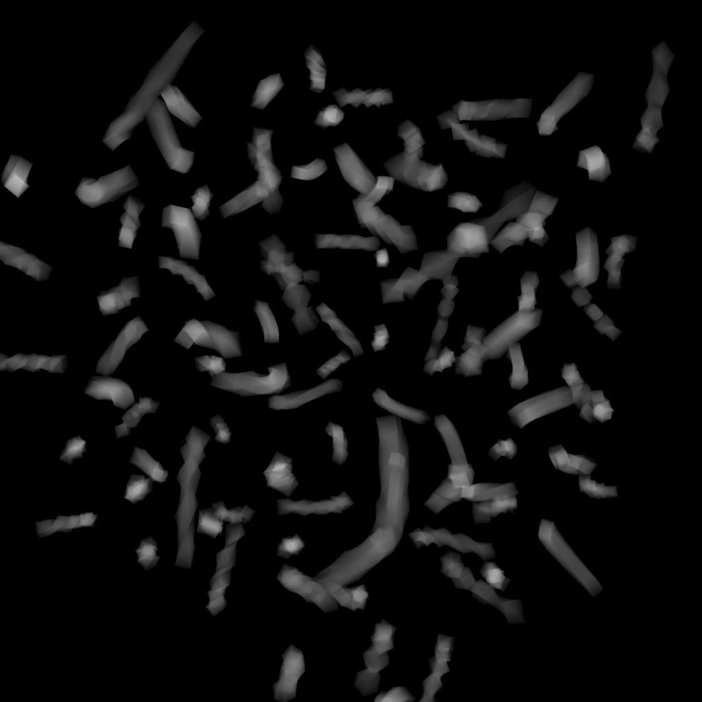
This property is valid only when Geometry motion blur is set to “Acceleration Blur”. Enter the name of a point attribute to use as the acceleration value when rendering multi-segment acceleration blur. The default is accel, which may be added to geometry automatically by various simulation solvers.
Controls anamorphic depth of field by changing the aspect ratio for the ellipse of confusion. Values between 0 and 1 will increase the amount of blur in the Y direction. Values larger than 1 will decrease the amount of blur in Y.
Controls the number of primary rays Mantra will use to sample your scene per pixel. The two numbers represent an arrangement of samples in the X and Y axis and are generally the same number. However, for non-square pixels it may be necessary to use different values in X and Y. Multiplying these two values together will give you the number of primary rays per pixel.
Increasing Pixel Samples will result in a cleaner, higher quality image. However, since all other sampling values are multiplied by the number of Pixel Samples, they should only be increased when necessary. For more details on when to increase Pixel Samples, see the “Removing Noise” section.
When enabled, this parameter will cause Mantra to use ray variance antialiasing when determining the number of Secondary Rays to send for every Primary Ray.
This means that rather than using a specific number of rays, Mantra will first send out a small number of rays and use this sample set to evaluate the Variance. Depending on the amount of variance, Mantra will continue to send more rays up to the Max Ray Samples value. Ray Variance Antialiasing is useful for optimizing your render by sending more rays only in the areas they are needed.
In cases where the minimum number of rays to remove noise is equal to the maximum number of rays, you may save a small amount of render time by disabling Ray Variance Antialiasing.
When Ray Variance anti-aliasing is enabled, this parameter represents the maximum number of secondary rays allowed for each BSDF type even if the Noise Level is never reached. This parameter, along with Min Ray Samples, essentially allows you to create a range of acceptable sampling for your image. Carefully controlling the total number of potential rays is the best way to optimize your renders.
Remember, this number is multiplied by the current number of Pixel Samples and the number of BSDF types on the material being evaluated. For example, if it’s a purely diffuse material, and Pixel Samples are set to 3×3, and the Max Ray Samples is set to 1, then it will cast up to 9 secondary rays (9 diffuse rays). If the material is both reflective and refractive, then it will cast up to 18 secondary rays (9 reflection and 9 refraction rays).
For more details on when to increase Max Ray Samples, see removing noise.
This value is the minimum number of secondary rays to use for each BSDF type when generating an image. When Ray Variance anti-aliasing is disabled, this number represents the number of secondary rays to send regardless of the Noise Level.
Remember, this number is multiplied by the current number of Pixel Samples and the number of BSDF types on the material being evaluated.
Represents a threshold in the amount of variance allowed before mantra will send more secondary rays. Variance essentially represents how “spread out” the values in a set of samples are. For instance, a set of samples that were all the same would have a variance of 0. It is generally a good idea to keep this value as high as possible so that rays are sent only into those areas where an unacceptable amount of noise is present.
Adding “direct samples” and “indirect samples” image planes can help you track how many samples are being sent and to which parts of the image. For more information about sampling, see the “Sampling and Noise” section.
If you find that certain objects in your scene require substantially more samples than other parts of your image and you are unable to “target” those objects using the Noise Level parameter, it may be a better idea to add per-object sampling parameters to the problem areas. See removing noise for more details.
Acts as a global multiplier on all per-component quality parameters. This allows you to increase/decrease quality, keeping the relative per-component qualities the same.
Controls the quality of indirect diffuse sampling (for information on the difference between direct and indirect rays, see sampling and noise). Often, indirect sources of light (such as the surfaces of other objects, and light scattered inside of a volume) will be a significant cause of noise in your renders. Turning this up should decrease this type of noise, at the cost of slowing down rendering.
This parameter acts as a multiplier on Min Ray Samples and Max Ray Samples and also as a divisor for Noise Level. For example, if you have Min Ray Samples set to 1, Max Ray Samples set to 8 and your Noise Level to 0.1, then set Diffuse Quality to 2, Mantra will send between 2 and 16 secondary diffuse ray samples based on a Noise Level of 0.05. Remember these numbers apply only to the indirect samples. Mantra uses the original values for all direct sampling.
To find how much noise is in your indirect diffuse component, add the “Indirect Lighting (per-component)” image plane in the Extra Image Planes tab. This lets you check each indirect component individually. For this parameter, you should check the Indirect Diffuse component.
Controls the quality of indirect sss sampling (for information on the difference between direct and indirect rays, see sampling and noise). Often, indirect sources of light (such as the surfaces of other objects, and light scattered inside of a volume) will be a significant cause of noise in your renders. Turning this up should decrease this type of noise, at the cost of slowing down rendering.
This parameter acts as a multiplier on Min Ray Samples and Max Ray Samples and also as a divisor for Noise Level. For example, if you have Min Ray Samples set to 1, May Ray Samples set to 8 and your Noise Level to 0.1, then set SSS Quality to 2, Mantra will send between 2 and 16 secondary SSS ray samples based on a Noise Level of 0.05. Remember these numbers apply only to the indirect samples. Mantra uses the original values for all direct sampling.
To find how much noise is in your indirect SSS component, add the “Indirect Lighting (per-component)” image plane in the Extra Image Planes tab. This lets you check each indirect component individually.
Controls the quality of indirect refraction sampling (for information on the difference between direct and indirect rays, see sampling and noise). Indirect refractions (refracted light from of other objects in the scene, such as when viewing an object through glass) can sometimes add noise to the render. Turning this up should decrease this type of noise, at the cost of slowing down rendering.
This parameter acts as a multiplier on Min Ray Samples and Max Ray Samples and also as a divisor for Noise Level. For example, if you have Min Ray Samples set to 1, May Ray Samples set to 8 and your Noise Level to 0.1, then set Refract Quality to 2, Mantra will send between 2 and 16 secondary refraction ray samples based on a Noise Level of 0.05. Remember these numbers apply only to the indirect samples. Mantra uses the original values for all direct sampling.
To find how much noise is in your indirect refraction component, add the “Indirect Lighting (per-component)” image plane in the Extra Image Planes tab. This lets you check each indirect component individually. For this parameter, you should check the Indirect Refraction component.
Controls the quality of indirect reflection sampling (for information on the difference between direct and indirect rays, see sampling and noise). Indirect reflections (reflections of other objects in the scene) can sometimes add noise to the render. Turning this up should decrease this type of noise, at the cost of slowing down rendering.
This parameter acts as a multiplier on Min Ray Samples and Max Ray Samples and also as a divisor for Noise Level. For example, if you have Min Ray Samples set to 1, May Ray Samples set to 8 and your Noise Level to 0.1, then set Reflect Quality to 2, Mantra will send between 2 and 16 secondary reflection ray samples based on a Noise Level of 0.05. Remember these numbers apply only to the indirect samples. Mantra uses the original values for all direct sampling.
To find how much noise is in your indirect reflection component, add the “Indirect Lighting (per-component)” image plane in the Extra Image Planes tab. This lets you check each indirect component individually. For this parameter, you should check the Indirect Reflection component.
Controls the quality of indirect volume sampling (for information on the difference between direct and indirect rays, see sampling and noise). Often, indirect sources of light (such as the surfaces of other objects, and light scattered inside of a volume) will be a significant cause of noise in your renders. Turning this up should decrease this type of noise, at the cost of slowing down rendering.
This parameter acts as a multiplier on Min Ray Samples and Max Ray Samples and also as a divisor for Noise Level. For example, if you have Min Ray Samples set to 1, May Ray Samples set to 8 and your Noise Level to 0.1, then set Volume Quality to 2, Mantra will send between 2 and 16 secondary volume ray samples based on a Noise Level of 0.05. Remember these numbers apply only to the indirect samples. Mantra uses the original values for all direct sampling.
To find how much noise is in your indirect volume component, add the “Indirect Lighting (per-component)” image plane in the Extra Image Planes tab. This lets you check each indirect component individually. For this parameter, you should check the Indirect Volume component.
Sampling color space for variance antialiasing. Setting this to Gamma 2.2 will cause darker parts of the image to receive more samples.
Decouples the Direct from Indirect Rays, allowing for different sampling rates as well as separate noise levels. Generally speaking, it will only be necessary to enable this parameter if you find that too many samples are being sent as Direct Rays.
Adding “direct samples” and “indirect samples” image planes can help you track how many samples are being sent and to which parts of the image. For more information about sampling, see the “Sampling and Noise” section.
This parameter will enable three new parameters: Min Indirect Ray Samples, Max Indirect Ray Samples, and Indirect Noise Level.
To understand the difference between Direct and Indirect rays, see sampling and noise.
The minimum number of indirect rays to use when generating an image. Generally speaking indirect rays are used when sampling other objects and their material properties. For more information about indirect rays see “Sampling and Noise”.
Remember, like the previous Ray Sample limits, this value is multiplied by the current number of Pixel Samples.
The maximum number of indirect rays to use when generating an image, even if the Indirect Noise level is never reached. This parameter, along with Min Indirect Ray Samples, essentially allows you to create a range of acceptable sampling for your image. Carefully controlling the total number of potential rays is the best way to optimize your renders.
Remember, this number is multiplied by the current number of Pixel Samples.
For more details on when to increase Max Indirect Ray Samples, see removing noise.
A threshold in the amount of variance allowed before mantra will send more indirect rays. Variance essentially represents how “spread out” the values in a set of samples are, a set of samples that were all the same would have a variance of 0. It is generally a good idea to keep this value as high as possible so that rays are sent only into those areas where an unacceptable amount of noise is present.
Adding “direct samples” and “indirect samples” image planes can help you track how many samples are being sent and to which parts of the image. For more information about sampling, see the “Sampling and Noise” section.
If you find that certain objects in your scene require substantially more samples than other parts of your image and you are unable to “target” those objects using the Noise Level parameter, it may be a better idea to add per-object sampling parameters to the problem areas. See removing noise for more details.
The relative number of illumination samples to be used for the light source. Sampling Quality is relative to the ray sampling parameters (vm_minraysamples and vm_maxraysamples).
A floating point value which adds noise to pixel sampling patterns. A value of 1 will fully randomize pixel sampling patterns, while a value of 0 turns of pixel jitter resulting in stairstep artifacts when too few pixel samples are used. Jitter only applies to pixel antialiasing and does not apply to motion blur or depth of field sampling (which are always randomized).
Adjusting this parameter will cause the pixel sampling patterns used by Mantra to be regenerated in different configurations. By default, the patterns change on every frame, so manually changing this value is not necessary.
Sampling generally occurs in random patterns which change on every frame of an animation. This can cause a distracting “buzz” when there is a significant amount of noise in your images which can make evaluation of other aspects of the scene difficult. Enabling this parameter will “lock” the sampling patterns so that the noise remains the same on every frame.
Also, in some cases where the final rendered images will be sent through a post-render de- noise process, it can be useful to have the noise remain constant frame to frame. Consistent sampling patterns can help when analyzing the noise.
It defaults to “off” because it is generally unacceptable to have a locked sampling pattern for final sequences.
Decorrelate Depth of Field from Motion Blur Samples
For scenes using both motion blur and depth of field, mantra’s default image sampling patterns correlate the time and depth of field samples. This has the effect of reducing noise, but can lead to correlation artifacts (banding) in the render in parts of the image where there is both significant motion blur and depth of field. Decorrelating depth of field from motion blur by enabling this setting will eliminate these banding artifacts while increasing the noise in the render.
For micropolygon rendering, there is a performance penalty when enabling this property, since mantra optimizes micropolygon rendering for correlated depth of field sampling patterns. There is no performance penalty for ray tracing.
Filter kernel used in depth of field rendering. Use the pop-up menu to the right of the text box to choose from the available options.
Radial bokeh (radial)
Use a gaussian filter kernel (highest quality).
Image file bokeh (file)
Use an image file
Box filter bokeh (box)
Use a box filter kernal.
Disable bokeh (null)
Do not filter.
The file to use for “file” shaped bokeh. White/black cutout images that delineate the shape of the lens are good candidates, where white regions represent the areas that light passes through.
A scale on the native step size that determines how finely mantra will subdivide the velocity blur ray tracing cage. For voxel volume primitives, the default of 0.1 means to take one velocity sample every 10 voxels. Smaller values will speed up renders but may introduce inaccuracy in the resulting motion blur.
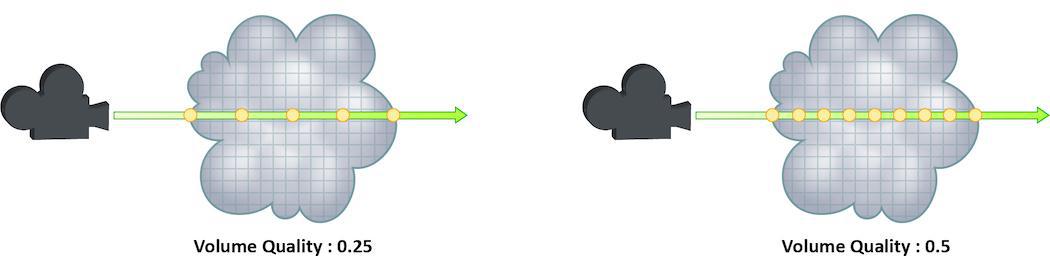
How finely or coarsely a volume is sampled as a ray travels through it. Volumetric objects are made up of 3d structures called Voxels, the value of this parameter represents the number of voxels a ray will travel through before performing another sample.
The default value is 0.25, which means that every one of every four voxels will be sampled. A value of 1 would mean that all voxels are sampled and a value of 2 would mean that all voxels are sampled twice. This means that the volume step rate value behaves in a similar way to pixel samples, acting as a multiplier on the total number of samples for volumetric objects.
For volumes that aren’t voxel based, like CVEX procedural volumes, Mantra will divide the bounding box of the volume into roughly 100 “virtual” voxels. In these cases, setting the Volume Step Rate correctly is essential to maintaining the correct level of detail.
Keep in mind that increasing the volume step rate can dramatically increase render times, so it should only be adjusted when necessary. Also, while increasing the default from 0.25 can reduce volumetric noise, increasing the value beyond 1 will rarely see similar results.
For more information about volume sampling, see sampling and noise.
Whether to render this object as if it was a uniform-density volume. Using this property on surface geometry is more efficient than actually creating a volume object of uniform density, since the renderer can assume that the volume density is uniform and place samples more optimally. The surface normal of the surface is used to determine which side of the surface will render as a volume - the normal will point away from the interior. The surface need not be closed - if the surface is not closed, the volume will extend an infinite distance away from the surface. Non-closed surfaces may produce unexpected results near the edge of the surface, so try to keep the viewing camera away from the edges. This parameter is compatible with ray tracing and PBR but not micropolygon renders.
Determines the type of uniform volume. Continuous samples along a series of points within the intersected volume object. Segment samples once per-segment within the intersected volume object.
Uniform volume flipped normal detection threshold
When there are flipped normals due to reversed geometry or self intersections, mantra may misjudge volume spans and cause artifacts in render. Mantra will try to correct for such a case, provided that the distances between the intersections fall within this threshold.
When rendering a uniform volume (vm_uniformvolume is enabled), this setting controls whether the surface is also rendered. If you enable this setting, the surface shader should handle both volume and surface samples by checking the value of the dPdz global - when it is 0 the shader should render a surface, otherwise a volume.
Rather than generating samples inside a volume, this setting will configure the renderer so that it automatically finds an isosurface of the volume density field and renders this as a surface. The vm_volumedensity parameter is used as a threshold to control the isosurface density threshold. You should use an ordinary surface shader when rendering volumes with this setting enabled - not a volume rendering surface shader.
By default, the isosurface is found by ray marching through the volume to find points where the threshold density is crossed. This means that to improve render accuracy, you can increase the vm_volumesteprate parameter. Some volume types use a native accelerated isosurface search technique in which case the volume step rate is ignored and the isosurface is determined analytically for that particular type of volume. VDB volumes, for example, use this analytic isosurface rendering approach. The vm_volumeisodefault parameter can be used to disable this native intersection algorithm.
Use default volume isosurface evaluator
Disable native volume isosurface for this object when vm_volumeiso is enabled. This parameter will only affect volume types that have a native isosurface algorithm - including VDB volumes.
When vm_volumeuniform is on, the uniform density of the object’s volume. This value must be the same on the object as on the Volume Cloud shader. When vm_volumeiso is on, this value specifies the threshold density value for isosurface rendering.
The number of samples to generate when rendering a uniform volume (vm_uniformvolume is enabled). The samples will be distributed so as to produce an equal image contribution if they were all equal in brightness.
A factor to proportionally decrease the volume step rate only for shadows, relative to the volume step rate. Smaller values will cause mantra to use a larger ray march step size for shadow rays than other shading rays. A value of 1 will produce equal quality for shadow rays and shading rays.
Specifies the minimum density value that will be rendered. Using a larger zero threshold can improve rendering performance by reducing the amount of shading and sampling that occurs in nearly empty parts of the volume. Using too large a zero threshold can introduce clipping artifacts in the render.
Specifies the volume channel by name that will be used for empty space culling. By default mantra will use the 'density' channel if it exists. If you are rendering an emissive volume in which some parts of the volume have a 0 density but still need to be rendered, you should specify a different channel using this parameter. If the specified channel is not found, mantra will assume that the entire volume needs to be rendered and no culling will occur. The sampling channel should be structured such that values less than the vm_volumezerothresh indicate empty space.
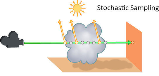
The number of transparent samples to be shaded as a ray travels through translucent objects. Increasing this value will result in less noise in translucent objects and is generally less costly than increasing Pixel samples, Volume Step Rate, or Min and Max ray samples. Stochastic Sampling will not have any effect on noise from Indirect Sources however.
This may make the image noisier than without stochastic transparency, so you may need to compensate by, for example, increasing the pixel samples. You should generally leave this option on.
The renderer ignores this option for micropolygon rendering (except for secondary ray tracing) and for renders that only generate opacity (such as deep shadow maps). In those cases it is more efficient to composite all the transparent shading results.
Added in Houdini 12.
The number of transparent samples to shade when Stochastic Transparency is on. Higher values improve shading quality for volumes and transparent surfaces, but are slower to render.
Occasionally, when motion blur is going to be added to an image as a post-process or for other compositing operations, it is necessary to calculate the motion blur but not include it in the final rendered image. In these cases, Allow Image Motion Blur should be disabled.
This means that the blurred positions necessary for Motion Blur can be exported as a custom Motion Vector Image Plane from within a shader using the GetBlurP() function without the small overhead of doing the actual shading in the render.
This parameter is related to the motion blur parameters which are available only when Motion Blur is enabled. Disabling this option will cause motion blur to be removed from the final rendered image, however the blurred Position will still be calculated, allowing for custom motion vector image planes to be created.
Shaders 
When the object has matte shading enabled, this shader is used for primary ray shading instead of the surface shader.
On object nodes, this parameter defines a material style sheet to be applied to this object' geometry. A material style sheet determines the geometry look by assigning various shaders and materials to different pieces of the geometry (primitives) and by overriding shader parameters for rendering just these pieces.
The style sheet definition in this parameter is specified using a JSON format, but can be edited in Data Tree pane with Material Style Sheets view.
Shading 
A space-separated list of component types that will behave like diffuse bounces. This will affect which reflection scope is used based on the ray type and also which bounce limit to use. Uncategorized component types are assumed to be reflections.
A space-separated list of component types that will behave like refract bounces. This will affect which reflection scope is used based on the ray type and also which bounce limit to use. Uncategorized component types are assumed to be reflections.
A space-separated list of component types that will behave like volume bounces. This will affect which reflection scope is used based on the ray type and also which bounce limit to use. Uncategorized component types are assumed to be reflections.
A space-separated list of component types that will behave like subsurface scatter bounces. This will affect which reflection scope is used based on the ray type and also which bounce limit to use. Uncategorized component types are assumed to be reflections.
Variables imported by fog shaders
To save on computation, mantra will only compute exports on surface shaders if the variable needs to be saved to an image plane. This means that some surface exports may not be available in fog shaders for the simport() function. This parameter specifies a list of variables which need to be computed for fog shaders.
Enable Absorption and Nested Dielectrics
To save on computation, mantra will only compute exports on surface shaders if the variable needs to be saved to an image plane. This means that some surface exports may not be available in fog shaders for the simport() function. However, to properly render advanced features like absorption and nested dielectrics, additional exports from surface shaders are required. This enables on these special exports.
The type of path tracing to perform in PBR mode.
specular, diffuse
Trace all diffuse and specular bounces, but once a diffuse bounce is encountered continue tracing only with diffuse reflections.
all
All paths are traced. This option can be used to enable rendering of caustics without the use of photon maps. However when using point or small area lights, the rendered result can turn out to be extremely noisy.
Constrain by Maximum Roughness
Roughness parameter in GGX BSDFs are clamped by the maximum roughness value propagated down the ray chain in pathtracing. Enabling this option can cut out a lot of noise in indirect specular (in particular, cases where glossy surface is reflected by a rough specular surface) at the cost of a bit of accuracy.
The shader used to evaluate samples for the experimental generator rendering engine.
The maximum bounds that the displacement shader will move geometry. This is defined in “camera” space. NOTE
The absolute value is used to determine the bounds.
The space in which you specify displacement bounds.
"object"
Displacements occur in object space.
"camera"
Displacements occur in camera space.
"world"
Default, currently an alias for camera.
The maximum bounds for volume velocity motion blur. It is only necessary to configure this parameter when using velocity motion blur with custom volume procedurals, since mantra already computes an accurate bound for built-in volume types.
With extreme displacement, it’s possible to get micro-polygons which are stretched far out of shape. Turning re-dicing on will cause the geometry to be re-measured after a trial displacement, to get a much better estimate of the actual size of the displaced geometry. This will result in micro-polygons which have a much more uniform size and will most likely provide higher quality images. This is more costly since the displacement shader may be run twice during the dicing process.
This property has no effect for volume displacements.
When enabled, the object’s surface shader will be replaced with a matte
shader for primary rays. The default matte shader causes the object to
render as fully opaque but with an alpha of 0 - effectively cutting a
hole in the image where the object would have appeared. This setting is
useful when manually splitting an image into passes, so that the
background elements can be rendered separately from a foreground
object. The default matte shader is the “Matte” VEX shader, though it
is possible to set a different matte shader by adding the
vm_matteshader render property and assigning another shader.
Secondary rays will still use the object’s assigned surface shader,
allowing it to appear in reflections and indirect lighting even though
it will not render directly.
For correct matte shading of volumes:
-
Add the
vm_matteshaderproperty to the object. -
Create a Volume Matte shader.
-
Set the density on this shader to match the density on the geometry shader.
-
Assign this shader to
vm_matteshader.
Then when the Matte Shading toggle is enabled, it will use your custom volume matte shader rather than the default (which just sets the density to 1). If you want fully opaque matte, you can use the matte shader rather than volume matte.
When running displacement shaders, whether the VEX variable P is actually moved (true displacement) or whether bump mapping will be performed.
Add Bump To Ray Traced Displacements
When true displacements is enabled, use the displacement as a bump map in addition to displacing the geometry. Enabling this option can increase apparent detail without incurring the cost of an increase in shading quality. Essentially, mantra is using true displacements up to the shading quality, and then adding the remaining detail by modifying the shading normal N.
Some volume primitives (Geometry Volumes, Image3D) can use a filter during evaluation of volume channels. This specifies the filter. The default box filter is fast to evaluate and produces sharp renders for most smooth fluid simulations. If your voxel data contains aliasing (stairstepping along edges), you may need to use a larger filter width or smoother filter to produce acceptable results. For aliased volume data, gauss is a good filter with a filter width of 1.5.
-
point -
box -
gauss -
bartlett -
blackman -
catrom -
hanning -
mitchell
This specifies the filter width for the object:filter property. The filter width is specified in number of voxels. Larger filter widths take longer to render and produce blurrier renders, but may be necessary to combat aliasing in some kinds of voxel data.
Shade every sample rather than shading micropolygon vertices. This setting enables the raytrace rendering on a per-object basis.
When micro-polygon rendering, shading normally occurs at micro-polygon vertices at the beginning of the frame. To determine the color of a sample, the corner vertices are interpolated. Turning on object:rayshade will cause the ray-tracing shading algorithm to be invoked. This will cause each sample to be shaded independently. This means that the shading cost may be significantly increased. However, each sample will be shaded at the correct time, and location.
Currently not supported for per-primitive material assignment (material SOP).
Global raytracing bias to be used for PBR rendering, specified in world space units. Increase the raytracing bias only if doing so eliminates rendering artifacts in your render. For really small scenes (1 unit in size), it is sometimes necessary to decrease the raytracing bias.
Controls the distance between the shading position and the generated points used for ray tracing derivative calculations as a multiple of the pixel size. Smaller values will produce sharper results at the expense of possible numerical stability problems. If you are using bump mapping on geometry with inconsistent tangent vectors, decrease this value to eliminate artifacts in the render. This value is not a scale on the derivative size, only an accuracy control.
Randomize ray derivative basis
When enabled, ray tracing derivatives will use a randomly oriented s/t basis as opposed to the default geometric basis. This property can be used to reduce shading artifacts that arise due to abrupt changes in parameter directions at surface boundaries, particularly when computing normals from high frequency patterns. Ray tracing derivatives include all values computed using the Du(), Dv(), computenormal(), and the dPds/dPdt globals. The s and t shading globals are unaffected by this property.
When micro-polygon rendering, shading normally occurs at micro-polygon vertices at the beginning of the frame. Enabling this checkbox causes the vertex colors to be Gouraud shaded to determine the color for a sample.
Turn this checkbox off when you are trying to match a background plate to eliminate any filtering which might occur on the plate. The Gouraud interpolation will cause softening of the map.
The space or comma separated list of categories to which this object belongs.
Currently not supported for per-primitive material assignment (material SOP).
A list of patterns. Lights matching these patterns will illuminate this object. You can use wildcards (for example, key_*) and
bundle references to specify lights.
You can also use the link editor pane to edit the relationships between lights and objects using a graphical interface.
The object:lightmask property in Mantra is a computed property containing the results of combining light categories and light masks.
Custom label assigned to lights or objects for use with light path expression.
A space-separated list of categories. Lights in these categories will illuminate this object.
A list of patterns. Objects matching these patterns will reflect in this object. You can use wildcards (for example, key_*) and
bundle references to specify objects.
You can also use the link editor pane to edit the relationships between lights and objects using a graphical interface.
The object:reflectmask property in Mantra is a computed property containing the results of combining reflection categories and reflection masks.
A space-separated list of categories. Objects in these categories will reflect in this object.
A list of patterns. Objects matching these patterns will be visible in refraction rays. You can use wildcards (for example, key_*) and bundle references to specify objects.
You can also use the link editor pane to edit the relationships between lights and objects using a graphical interface.
The object:refractmask property in Mantra is a computed property containing the results of combining reflection categories and reflection masks.
A space-separated list of categories. Objects in these categories will be visible in refraction rays.
When biases are used in VEX shaders, the bias can either be performed along the ray direction or along the surface normal. If this parameter is turned on, biasing will be along the surface normal - using the Ng VEX variable.
If the ray direction and normal point in different directions, the normal will first be flipped and then biasing will be performed in the direction of the flipped normal. This setting is particularly useful when ray traced surfaces that are seen edge-on.
Normally, emission (“Ce”) will contribute to secondary rays such as reflections. This setting disables emission for secondary rays so that it only affects primary rays or directly visible light. This setting is useful to avoid double-counting emission when it is already handled by another object or light.
Share Displacements Between Instances
By default, when instancing is used with displacements, the displaced geometry will be created uniquely for each instance, since it’s possible that the displacements may differ based on the world-space position of each instance. This default behavior will guarantee correct results but it can be inefficient since mantra needs to keep a separate copy of the displaced geometry for each instance. When this setting is enabled, mantra will share a single copy of the displaced geometry between all instances, and assumes that the displacement shader only uses the object space position to determine the displaced position and normal.
The dicing quality used when displacements are shared will be the dicing quality for the instance that is closest to the camera. Therefore, instances that are farther from the camera may incur a greater rendering cost when this setting is enabled, but overall memory use will usually be lower.
When sharing displacements on packed primitives, there’s a very subtle issue which may cause issues with popping displacements. The vm_procuseroottransform toggle is on by default. This means the object space for the packed geometry will not include the transform on the packed primitive itself, only the transform on the object containing the packed primitives. This is important when doing geometry/volume lighting so that point clouds will all be in the space of the single object. However, when there are shared displacements, the displacement should be computed in the space of the unpacked geometry (i.e. including the transform on the packed primitive). If you want to use shared displacements on packed primitives, you should turn off the vm_procuseroottransform parameter.
Shadow 
Statistics 
VEX profiling lets you do analyze shader performance. Turning this on will slow down shading, especially when NAN detection is turned on.
No VEX Profiling (0)
No VEX Profiling is performed.
Execution Profiling (1)
Mantra will print out information about shading computations at the conclusion of the render. This helps in identifying bottlenecks in the shading process.
Profiling and NAN detection (2)
Prints out the shading information and will not print instructions that generate bad values (Not A Number). The output is cryptic, but can help track down errors in shaders.
When NAN detection is turned on, each instruction executed in VEX will be checked for invalid arithmetic operations. This will check for division by 0, numeric overflow, invalid operations. Errors like this will typically result in white or black pixels in the resulting image.
Increasing this value will cause more information to be printed out during rendering. To see render time and memory information, set the verbosity level to 1. To see more detailed information about the render, set this parameter to 3. Larger values print out progressively more information.
A percentage complete value is printed out as tiles are finished. This is in the style expected by Pixar’s Alfred render queue.
The following is an example of timing information and how to read it.
Render Time: 4.52u 6.30s 4.24r Memory: 23.40 MB of 23.59 MB arena size. VM Size: 345.11 MB
-
The
uvalue is the user time in seconds mantra took to render the image.Note
This value might not be 100% accurate depending on the OS and other system variables. On Linux, this value will indicate the total time for all threads to render, so rendering with more than one processor may inflate the user time.
-
The
svalue is the system overhead incurred in rendering the frame (disk io, swap, etc.). A large system time may indicate a large amount of time spend reading or writing files. -
The
rvalue is the wall clock time to render. This is the most important value as it gives a clear indication for the total amount of time spent rendering. -
Arena size is the amount of memory mantra allocated to actually render the image. It does not reflect how much memory mantra actually used.
-
VM size is the virtual memory size for the mantra program. This is the amount of memory reported by the operating system and may significantly exceed the amount of memory that mantra is actually using.
Mantra needs to grab continuous chunks of memory as it builds the data structures. Once it frees up the data, the operating system controls the arena size shrinking it where it finds continuous chunks of memory back to the free pool of available memory. This is called memory allocation and memory deallocation. You don’t want the arena size much larger than the actual memory used.
This property specifies a python callback which can be called at the completion of each tile rendered. There is a “built-in” “mantra” module which allows information to be queried. There is a single function available in the mantra module. The “property” function allows querying of any global rendering property as well as some other special properties. The result of the property call is always a list of values.
The special properties queried may be…
tile:ncomplete
The number of tiles which have been completed.
tile:ntiles
The total number of tiles in the image.
tile:laptime
The number of seconds taken to render the last tile.
tile:totaltime
The total number of seconds to render since the render began. This does not include time to load the scene, but rather is defined as the time since the first tile began rendering.
tile:coords
The tile bounding box (in pixels).
tile:memory
The amount of RAM in use by mantra.
import mantra
import sys

tile = mantra.property("tile:ncomplete")(0)
if tile == 1
    print mantra.property("renderer:name")
    print mantra.property("renderer:version")
Stereo 
Specifies a list of cameras to be used for rendering. The native operator type for the stereo camera has this property and by default specifies two regular cameras for the left and right points of view.
Is a string appended to the file name. This string is usually specified by the cameras included in the vm_cameralist property of another camera, and is appended to the vm_picture file name string of the render node before saving the rendered image to a file. It is used for disambiguating left and right images for a given frame. This suffix is added to the base filename and will come before the filename extension.
Unwrapping 
Selects the method used to unwrap from the 'UV Object'.
UV To Surface
Maps the UVs to their locations on the surface of the object.
Trace Closest Surface
Uses raytracing to find the surface closest to the UV Object.
The texture baking output format:
UDIM
Bake texture into one or more UDIM texture images.
Ptex
Bake texture into a single Ptex image.
When texture baking to UDIM images, this is the name of the texture coordinate attribute used for unwrapping.
When texture baking to UDIM images, this specifies the resolution of the UDIM images.
Create Intermediate Directories
When performing texture baking, this parameter will create any intermediate directories before creating the baked texture images.
When UV baking from a high-res object to a low-res cage, normally you want to turn off rendering of the low-res cage. Turning off this option will disable that feature.
This parameter controls the light components excluded during bake renders. When baking it is common to render only view-independent components such as “diffuse”. The default value of -diffuse & -volume will only render diffuse and volume light paths.
When baking to a Ptex image, this specifies the tile resolution for the smallest faces in the model.
When baking to a Ptex image, this specifies the largest resolution for any individual face in the model.
When baking to a Ptex image, mantra will measure the world-space size of all the faces in the image. Each face’s tile resolution will be determined by the relative size of the face compared with the smallest faces in the model (unless Ptex Use Relative Scale is disabled). The tile resolution of a given face is given by clamp(curr_size/min_size * ptexmapminres * ptexmapscale, ptexmapminres, ptexmapmaxres).
When baking to a Ptex image, mantra will look for primitive-level scalar attribute of this name to scale tile resolution of current face. Note that the scaled resolution is still clamped by Minimum and Maximum resolutions.
If this is disabled, mantra will no longer measure relative size of faces compared with smallest faces in the model when baking to a Ptex image. The tile resolution of each face will simply be Minimum Ptex Map Resolution multiplied by Ptex Resolution Scale and primitive-level Ptex scale attribute (if one exists).
Orient Ptex Subfaces Clockwise
When baking to a Ptex image, this option determines the orientation of face ids for subfaces when splitting non-quad faces. The default is to order the sub-faces counterclockwise. However, some software expects to have the faces ordered clockwise.
When baking to a UDIM image, this option determines what type of post-processing is applied to the final image. The choices are No Post Processing, Border Expansion, Fill Background With Average Color, and Diffuse Fill.
Note
Currently, this is only supported when rendering to disk (not to flipbooks)
UV Additional Pixels at Border
When baking to a UDIM image and performing island border expansion, this parameter indicates by how many pixels each island should be enlarged.
When texture baking, this will reverse normals on the geometry. This determines the orientation of the surface for the baking lens shader (i.e. shade the inside or outside of the surface).
Determines how much to offset the position of the ray from the surface of the object along the normal vector. This value should be increased proportional to the displacement in a displacement shader (if there is one) in order to ensure that the ray hits the surface. The bias is used solely for camera rays.
User 
View 
The output resolution in pixels. Standard presets are available via the pull down menu to the right of the parameter.
Type of camera projection used for rendering (for example, perspective or orthographic).
Perspective
This simulates the classic pinhole camera where camera rays emanate from a common camera origin through a flat camera plane.
Orthographic
This uses parallel camera rays that are orthogonal to the (flat) camera plane. The width of the view volume is determined by the Ortho Width parameter below.
Polar (panoramic)
This projection uses a spherical camera plane for rendering.
Cylindrical (panoramic)
This projection uses a cylindrical camera plane for rendering.
Lens Shader: Use a lens shader to initialize rays for ray tracing.
Selecting Polar, Cylindrical or Lens Shader will automatically switch the Rendering Engine (on the output driver) to Ray Tracing, as it is impossible to render these projections with micropolygon rendering.
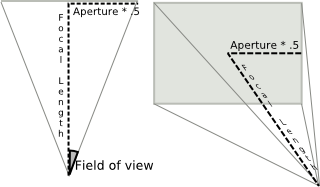
Width of the visible field.
You can obtain a good fit between the Houdini camera and a real world camera by matching a measured lens’s horizontal angle of view, and deriving a Houdini focal length value that reproduces it with the default aperture 41.4214.
Note
The default aperture combined with the default focal length of 50mm produces a 45 degree field of view.
Enlarges the crop region by this many pixels (horizontal and vertical amounts). If the crop region is the full image, additional pixels outside the image will be rendered.
For images that support arbitrary data windows (OpenEXR, Houdini) pixels outside the image resolution will be saved. For other image formats, the pixels will be computed but the results discarded.
Mantra is able to render using a non-flat projection plane. When the curvature is non-zero, ray-tracing will be used for primary rays. The curvature may either be greater or less than zero to mimic a wide angle or fish-eye lens.
The vm_curvature has the following effect on an existing perspective direction vector D:
tx = [-0.5:0.5] x screen offset
ty = [-0.5:0.5] y screen offset

cmult = camera:curvature / camera:zoom
D.z = 1 + (1 - 2*(tx*tx + ty*ty)) * cmult
Remove camera scaling when calculating the view transform. This is on by default.
Specifies a deep camera/shadow image to use to fill in the background color for primary rays (and only primary rays).
Because the deep camera/shadow image stores the color/opacity values for all depths, the deep image can be mixed with other objects in the scene with perfect occlusion/transparency.
Add this property to a camera (not the output driver). If you add it to the output driver, the background image will be picked up for shadow map generation, which is probably not what you want.
If you add this property to a light, the image will be merged with shadow maps generated shadow maps from the light.
Mantra uses OCIO to color correct images on disk. It may be able to guess the image’s color space based on the image filename (for example, myimage-srgb.exr) or format.
Render the background deep camera map as a matte object. When this property is on, mantra throws away the color of the deep camera map, and the alpha from the deep camera map is not put into the final image. This is the default behavior for deep shadow map files.
Only meaningful for deep camera images. Deep shadow images have this behavior by default.
A space/comma-separated list of patterns matching the channels to use from the background image. This For example, *,^C uses all channels except the C channel. This lets you for example use only the alpha channel from a deep camera map, and prevent the color from the DCM from affecting the rendered image.
This is applicable to both deep camera map backgrounds and flat image backgrounds.
Scale background to fill image
When enabled, if the background image does not match the render resolution the background will be scaled to fill the render resolution.
This setting allows you to apply a scale to the z-values in the background image, which may simplify merging deep images that have a different scale.
Specifies the CVEX lens shader to use for the Lens Shader projection
type. A lens shader is responsible for computing primary rays from
screen coordinates, and is a flexible way to define new kinds of camera
projections that can’t be modeled as perspective or orthographic
projections. Lens shaders can have the following parameters and
exports:
float x
X screen coordinate in the range -1 to 1.
float y
Y screen coordinate in the range -1 to 1.
float Time
Sample time.
float dofx
X depth of field sample value.
float dofy
Y depth of field sample value.
float aspect
Image aspect ratio (x/y).
int xres
Image horizontal resolution.
int yres
Image vertical resolution.
export vector P
Ray origin in camera space.
export vector I
Ray direction in camera space.
export int valid
Whether the sample is valid for measuring.
The lens shader should be able to handle x and y values outside the -1 to 1 range, in case samples outside the image need to be generated. The P and I exports should be created in camera space, ignoring the camera transform.
Before rendering begins, mantra measures the lens shader before
rendering. During the measuring process, the valid variable can be used
to flag invalid rays. In the future, the valid flag may be used during
rendering.
Mantra’s camera space is defined with positive z-values in front of the camera, so for a default camera the z-axis is flipped relative to Houdini’s world space.
An example lens shader is the ![]() Ray Lens shader.
Ray Lens shader.
Other Houdini properties 
The shader assigned to the automatically added background fog object (see vm_fogbackground). You must add this as a spare parameter if you want to change it, it doesn’t exist in the render properties interface.
The number of tiles queued for network rendering. You must add this as a spare parameter if you want to change it, it doesn’t exist in the render properties interface.
Typically handled automatically during IFD generation.
In the material overrides, the names specified for the overrides may not
match the internal mantra property names (i.e. vm_rendersubd as opposed
to rendersubd). The property map provides a name map (represented as a
Python dictionary) mapping the parameter name specified in the override to
the actual Mantra property name.
You must add this as a spare parameter if you want to change it, it doesn’t exist in the render properties interface.
Enables independent sampling for different light sources when rendering with PBR. When disabled, mantra will attempt to reduce the expense of lighting computation by randomly selecting a light source to compute illumination rather than performing lighting from all lights. Normally leaving multi-light sampling enabled will produce a better performance/quality tradeoff, in combination with active radius control in scenes with many lights.
This is passed as an argument to the vm_pbrshader.
You must add this as a spare parameter if you want to change it, it doesn’t exist in the render properties interface.
IFD-only properties 
These properties exist in IFD scene description files, but do not have equivalents in the Houdini property UI.
This is typically handled automatically using the camera shutter information.
Image and plane properties 
The name of the image file to write the plane to (if undefined, inherited from image:filename).
Name of a light object associated with the VEX variable. If this is set, the variable is exported at the conclusion of the illuminance loops run for the light.
The storage type for the plane image. The type of quantization used will affect image quality and size. If you need to adjust the image’s dynamic range in compositing, you should normally leave this value at the default of 16-bit floating point.
The default is "float16" for the first plane, and "float" for secondary planes. You can override the first plane’s value with the -b command line argument to mantra.
Implicit properties 
These properties are only meaningful in IFD:
Example: (9, 0, 614)
Read only triple of the major version, minor version, and build number of the renderer.
Example: (0)
An integer value which can be queried from within shaders. Not supported for per-primitive material assignment (in the ![]() Material surface node).
Material surface node).
Example: (1.0)
Read only floating point value that provides the surface area of the object currently being shaded.
Example: (1)
Read only integer value that indicates whether the current light (for example in an illuminance loop) is an area light.
Computed properties 
The following properties are computed in scripts during the mapping process. They do not have directly equivalent Houdini properties.
A rectangle in screen space as (xmin, xmax, ymin, ymax), where the values are between 0 and 1. Only pixels within this region will be rendered.
This is used in determining the camera projection. Like the crop window, this specifies a rectangle in the screen. Unlike the crop window, the window is expanded to fill the full image.
This property is used when computing the projection matrix for light sources in shadow mapping. If the projection from the texture is used (default behavior), this property is ignored.
The camera’s projection model. This may be one of perspective, orthographic, polar, or cylindrical.
Ratio of the focal length to the aperture of the camera. It is used to determine the field of view of the camera.
Not an intrinsic mantra property, but added by SOHO when rendering stereo pairs.
This is used to determine whether a camera represents the left eye or the right eye in a stereo projection. If stereo is not enabled for the camera, this property is undefined.
If defined, the value may be one of left, right, or both.
The name associated with the geometry. This is the name which instance objects use to access the geometry.
Materials may be specified on a per-primitive basis. However, since materials refer to SHOP paths, it’s sometimes important to be able to resolve relative paths.
This is a light shader used to handle geometry light intersections. This is used to implement the sample_light() function for area lights. This light shader cannot reference any global variables or light-specific functionality.
This is a light shader used to handle geometry light intersections. This is used to implement the intersect_lights() function for area lights. This light shader cannot reference any global variables or light-specific functionality.
Misc. properties 
A literal string to use as the “descriptive text” displayed with the
render node in the network editor. Usually, you will want to set
soho_descriptiveparmname instead, since it’s more useful to show the
value of a parameter instead of a static string.
The internal name of a paremeter to use as the content of the “descriptive
text” displayed with the render node in the network editor. For example, if
you set this camera, the network editor will display the value of the
render node’s Camera parameter beside the node in the network editor.
vm_motiontimescale / geometry:timescale
When the -v option is specified on the ray_detail line, this determines the time scale for velocity based motion blur.
You must add this as a float spare parameter if you want to change it, since it doesn’t exist in the render properties interface.
Is a spare parameter on the camera that will influence which objects are captured by the camera. This parameter is also recognized in the viewport, so if the camera has this parameter defined, when viewing through the camera the viewport will use it as a mask to filter which options should be visible.
Add an extra image plane for the shading position (P) using pre-defined settings. For finer control, add the image channel using the generic image plane interface.
Add an extra image plane for the shading depth (Pz) using pre-defined settings. For finer control, add the image channel using the generic image plane interface.
Add an extra image plane for the shading normal (N) using pre-defined settings. For finer control, add the image channel using the generic image plane interface.
Shading tangent-space normal (Nt)
Add an extra image plane for the shading tangent-space normal (Nt) using pre-defined settings. For finer control, add the image channel using the generic image plane interface.
This is specific to texture baking and exists by default on the baking output driver.
Combined lighting (per-component)
Add an extra image plane for the combined lighting (all components) using pre-defined settings. For finer control, add the image channel using the generic image plane interface.
Direct lighting (per-component)
Add an extra image plane for the direct lighting (all components) using pre-defined settings. For finer control, add the image channel using the generic image plane interface.
Indirect lighting (per-component)
Add an extra image plane for the indirect lighting (all components) using pre-defined settings. For finer control, add the image channel using the generic image plane interface.
Add an extra image plane for all types of light emission using pre-defined settings. For finer control, add the image channel using the generic image plane interface.
Add an extra image plane for the direct, un-shadowed lighting using pre-defined settings. For finer control, add the image channel using the generic image plane interface.
Add an extra image plane for the number of direct shading samples using pre-defined settings. For finer control, add the image channel using the generic image plane interface.
Add an extra image plane for the number of indirect shading samples using pre-defined settings. For finer control, add the image channel using the generic image plane interface.
Add two extra image planes for single and multiple subsurface scattering using pre-defined settings. For finer control, add the image channel using the generic image plane interface.
Used when baking textures. The high-res object’s normal projected into the low-res object’s tangent-space.
Used when baking textures. Stores the magnitude between the high-res and low-res objects.
Used when baking textures. Stores the deltas between the high-res and low-res objects.
Tangent-Space Vector Displacement (Vdt)
Used when baking textures. Stores the deltas between the high-res and low-res objects in the low-res object’s tangent-space.
Used when baking textures. The occlusion along the inverted normal at the shading position. This produces “relief” shading.
Baking Properties 
Disables all lighting on primary image plane in order to make baking faster.
Add Baking Exports to Shader Layers
Add baking related shader exports to layers structs, so they can be mixed by layer compositing operations and finally exported.
Number of samples to use for raytraced shading (eg. Occlusion, Cavity, Thickness). Increasing the number of samples will reduce noise in the shading.
Use Mikkelsen’s Tangent Space for baking tangent space normals (Nt). The basis is computed per-fragment (Unreal Engine compatible). Use a ![]() Divide SOP to convert the UV Object into triangle mesh before baking because other applications may interpolate tangents across quads differently.
Divide SOP to convert the UV Object into triangle mesh before baking because other applications may interpolate tangents across quads differently.
When enabled, backfacing normals in tangent space (i.e. its Z axis in tangent basis is negative) will be flipped to always face forward.
Toggles flipping of the normal’s X axis. Various packages may expect normal maps in different spaces. The flip parameters allow you to match these various spaces.
Toggles flipping of the normal’s Y axis. Various packages may expect normal maps in different spaces. The flip parameters allow you to match these various spaces.
This acts as a contrast control over the occlusion shading, with values higher and lower than 0.5 resulting in more and less contrast.
This acts as a contrast control over the cavity occlusion shading, with values higher and lower than 0.5 resulting in more and less contrast.
This is a course but fast approximation for measuring curvature. When off (the default), the renderer measures curvature using local topology. Turning this on measures curvature by casting occlusion rays. The number of occlusion rays is controlled by Baking Samples parameter.
Multiplies the output curvature value. If you are seeing any curvature shading you should increase this value until the gradient is visible.
This acts as a contrast control over the curvature’s shading, with values higher and lower than 0.5 resulting in more and less contrast.
Used to specify UDIM tiles to bake. Example: “1001-1004,1011” (without quotes). If left blank, mantra will bake all UDIM tiles the UV object occupies.
These controls let you output VEX variables as auxiliary image planes, either as extra planes in the output file or extra files.
Tip
As of Houdini 9.1, each channel can now be written out to a different file. This lets you work with OpenEXR programs that don’t support multiple channels in a single .exr image.
You can also do fancy stuff like send one channel to the md device (a non-interactive MPlay window), or split your image into multiple .pic files with a handful of .tif files thrown in. But if the primary image is ip, all planes go to ip.
The Channel Name parameter lets you give the channel in the output file a different name than the default (the name of the VEX variable). For example, you want to send out the Of variable. If the Channel Name is left blank, the plane name in the .pic file will be Of. If you set Channel Name to Opacity, the plane in the .pic file will be called Opacity.