| On this page |
Welcome 
Welcome to the introduction tutorial for Houdini 11. This tutorial covers the basics of the Houdini interface in quick chunks of information.
Viewing the scene 
Space is the “view key” in Houdini.
Holding down Space activates the ![]() View tool.
View tool.
While you hold down the space bar, the mouse buttons control the view, and hotkeys change to view-specific functions.
You can select the ![]() View tool in the toolbox (to the left of the 3D view) for continuous viewing without having to hold down Space.
View tool in the toolbox (to the left of the 3D view) for continuous viewing without having to hold down Space.
Move the mouse over the 3D view.
Hold Space and drag |
To… |
|---|---|
|
|
|
|
|
|
Display options 
Various controls around the interface let you control the scene display.
Use the viewport menus to set options related to the 3D view. Move the mouse over a viewport and press Space + B to switch between single and multi-viewport layouts.
Press D in the viewer to bring up a window of display options.
The display toolbar down the right side of the 3D view has controls for showing and hiding various components and features in the view.
Viewport layout 
You can divide the 3D viewer into several viewports displaying different views, or use one large view.
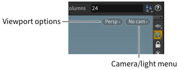
The floating menus in each viewport control viewing source, direction, and options for each viewport.
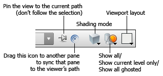
Use the ![]() viewport layout menu in the viewer toolbar to choose the layout. The icon changes to show the selected layout.
viewport layout menu in the viewer toolbar to choose the layout. The icon changes to show the selected layout.
Shading modes 
The shading mode controls how Houdini draws objects and geometry in the viewer.
You can also set different display profiles for selected, unselected, and other types of geometry. Move the mouse over the view and press D to open the display options window, then use the options on the Guides and Markers tab.
Press W to quickly switch between wireframe and shaded mode.
Click the ![]() shading menu on the toolbar across the top of the viewer to choose a shading mode.
shading menu on the toolbar across the top of the viewer to choose a shading mode.
Using the shelf 
The shelf across the top of the main window contains commonly used tools and commands.
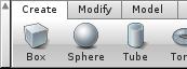
Click the ![]() Box icon on the shelf, then move the cursor over the 3D view.
Box icon on the shelf, then move the cursor over the 3D view.
Click to place the box in the scene, or press Enter to place it at the origin.
Object nodes and surface nodes 
Geometry objects consist of a Geometry container object, and surface nodes inside.
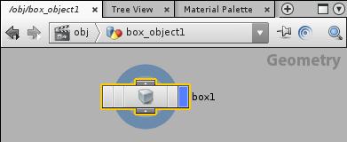
When you put down the box, Houdini created a Geometry container node at the top (“Scene”) level of the network. The node appears in the network editor pane.
If you double-click the box object in the network editor, you will go inside the Geometry container to the “Geometry” level, where surface nodes define the shape of the object by creating and manipulating curves and surfaces.
Click the ![]() Back button to go back to the Scene level.
Back button to go back to the Scene level.
Selecting objects 
You can select whole objects with the object selection mode and the Select tool.
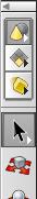
Click the ![]() Object selection mode icon at the top of the toolbox (on the left side of the 3D view).
Object selection mode icon at the top of the toolbox (on the left side of the 3D view).
Click the ![]() Select tool. This tool lets you select objects in the 3D view.
Select tool. This tool lets you select objects in the 3D view.
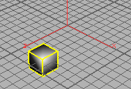
Click the box object to select it if it’s not already selected.
Click in empty space to de-select the box object.
Handles 
Handles let you directly manipulate objects and operations in the view.
Select the box object and then click the ![]() Move tool.
Move tool.
Drag the arrows to move the box along the X, Y, or Z axes. Drag the square in the center to move the box along the construction plane.
Parenting objects 
Parents apply their transformations to their children.
Normally an object may “jump” position as it assumes its parent’s transforms. To prevent this, when you select the child object, turn on Keep position when parenting in the parameter editor before you parent it.
To parent one object to another…
-
Select the child object.
-
Click
 Parent in the Modify shelf.
 -
Click the parent.
or
Connect the parent node’s output to the child node’s input in the network editor.
Selection mode 
The selection mode controls whether you are working on objects or components, and which type of components
In object mode, you select objects, such as geometry containers, lights, cameras, and characters.
In component mode, you select geometry components, such as points, faces, edges, and vertices.
Click the ![]() Object mode icon for object selection mode.
Object mode icon for object selection mode.
In object mode, the ![]() Select tool is a black arrow.
Select tool is a black arrow.
Click the ![]() Component mode icon below the object mode icon for component selection mode. The icon on the component selection mode button changes to show the current component type.
Component mode icon below the object mode icon for component selection mode. The icon on the component selection mode button changes to show the current component type.
In component mode, the ![]() Select tool is a white arrow. This is just another way to tell which mode you're in.
Select tool is a white arrow. This is just another way to tell which mode you're in.
You can also press F8 to switch between object and component mode, or use the 1-4 keys to switch between selection types.
Component type 
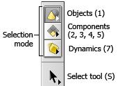
In component selection mode, you can choose which type of component to select.
Points lets you select the points at the corners of polygons, or the CVs of NURBS curves or surfaces.
Edges lets you select the polygonal edges between points.
Primitives lets you select polygonal faces, NURBS surfaces, and metaballs.
Vertices lets you select UVs and individual polygonal vertices. When polygons are fused together, one point can represent several vertices.
Right-click the selection mode button (below the ![]() Object selection mode button) and choose Primitives.
Object selection mode button) and choose Primitives.
Selecting components 
You can select components of an object (such as points, faces, and edges) with the component selection mode and the Select tool.
Note that in object mode, the select arrow is black, and in component mode it’s white. This is just another way of indicating which mode you're in.
Click the ![]() Select tool. This tool lets you select things in the 3D view.
Select tool. This tool lets you select things in the 3D view.
Click faces of the box to select them.
Because you have geometry components selected, the viewer, parameter editor, and network editor change to show the geometry inside the object. If you switch back to ![]() object selection mode, the panes switch back to the scene level.
object selection mode, the panes switch back to the scene level.
Editing components 
To edit components, select them and and use tools such as move, rotate, and scale.
When you have points, faces, or edges selected, the ![]() Move,
Move, ![]() Rotate, and
Rotate, and ![]() Scale tools affect the selected components.
Scale tools affect the selected components.
-
Press and hold on the component mode icon (below the
 Object selection mode icon), and choose
  Points.
 -
Click the
 Select tool and then select points on the cube.
 -
Click the
 Move tool and use the handle to move the selected points.
Parameters 
Parameters are the options of a node. They control how a node affects the scene.
Switch to ![]() object mode (press 1) and select the box. The parameter editor shows the parameters for the geometry container object. The object has parameters for transformations, as well as overall parameters for lighting and shading of the object which you can override at the geometry level.
object mode (press 1) and select the box. The parameter editor shows the parameters for the geometry container object. The object has parameters for transformations, as well as overall parameters for lighting and shading of the object which you can override at the geometry level.
Switch to ![]() component mode (press F8 or one of the number keys from 2 to 5). The parameter editor shows the parameters for the last surface node at the geometry level inside the object container, which is the Box node that creates the box (cube) geometry. The Box node has parameters that control what geometry type the box geometry is created from, its initial position, orientation, and size, and topology.
component mode (press F8 or one of the number keys from 2 to 5). The parameter editor shows the parameters for the last surface node at the geometry level inside the object container, which is the Box node that creates the box (cube) geometry. The Box node has parameters that control what geometry type the box geometry is created from, its initial position, orientation, and size, and topology.
You can quickly edit a parameter by pressing ![]() on the parameter name, or in one of the text box. The value ladder lets you adjust values interactively in small or large increments.
on the parameter name, or in one of the text box. The value ladder lets you adjust values interactively in small or large increments.
Ctrl-middle click a parameter to return it to its default value, or right-click the parameter and choose Revert to Default.
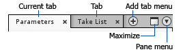
Using panes and tabs 
Panes divide the main interface into smaller areas devoted to specific tasks.
The initial pane layout has a large viewer pane, a parameter pane in the top right corner, and a network pane in the bottom right.
-
Drag the dividers between panes to resize them.
-
Press ⌃ Ctrl + B with the mouse pointer over a pane to expand that pane. This is especially useful over the viewer in the default layout, as a way to toggle the parameter and network panes.
-
To add a tab to a pane, click the
 new tab menu button (to the right of the tabs) and choose a pane type from the New pane tab type submenu.
 -
To change the type of pane in a tab, right click the tab and choose a type from the menu.
-
You add new panes by splitting an existing pane. Click the
 pane menu button (in the top right corner of the pane you want to split) and choose Split pane left/right or Split pane top/bottom.