| On this page |
|
Overview 
In Houdini, you can always switch to the camera tool in the viewer by pressing ⎋ Esc or holding Space or Alt. Then you can use the mouse to change the view.
For using a 3D mouse, please see the 3D mouse input page.
(You can turn off Use Alt Key for View Controls in the main preferences.)
Note
If you're used to 2D graphics applications, remember that in Houdini, “zooming” means changing the focal length of the virtual camera lens, not enlarging the view.
Tumbling, tracking, and dollying 
Space + |
|
Tumble |
Space + |
|
Dolly |
Space + |
|
Track |
Space + ⌃ Ctrl + |
|
Tilt the camera |
Space + ⌃ Ctrl + |
|
Zoom the camera lens |
⌃ Ctrl + Alt + |
Box zoom. Drag the box from left to right to zoom in on the area inside the rectangle. Drag the box from right to left to zoom out (so the current view fits inside the rectangle). |
|
⌃ Ctrl + Alt + |
Box crop. Drag the box from left to right to crop to the area inside the rectangle. Drag the box from right to left to reset to an uncropped view. Changing the crop area while looking through a camera that is not tied to the view will ignore that camera’s corresponding parameters until reset to an uncropped view or a new camera is used. |
|
⌃ Ctrl + Alt + |
Screen Pan. Pan the screen window of the camera (the camera position does not change) Panning the screen window while looking through a camera that is not tied to the view will ignore that camera’s corresponding parameters until reset to an uncropped view (see box crop above) or a new camera is used. |
|
Space + Z |
Set the tumble pivot to the point under the cursor and shift the camera so the new pivot is centered in view. The camera orientation is unchanged — only the camera position moves, preserving any intentional tilt or roll. |
|
Space + H |
Home: center the view to show all objects/geometry. If the |
|
Space + G |
Center the view on all selected objects/geometry. You can also press Space + F to center the view without rotating the angle. |
Tip
Hold ⇧ Shift while tumbling, dollying, tracking, or tilting for more precision.
View pivot 
You can choose to tumble, dolly, and zoom based on the view center, or based on the mouse position.
| To... | Do this | ||||||||||||
|---|---|---|---|---|---|---|---|---|---|---|---|---|---|
|
Set the tumble, dolly, and zoom modes |
In the
Alternatively, you can right-click the |
Tumbling 
Tumbling can pivot ![]() around the center of the scene (effectively), or
around the center of the scene (effectively), or ![]() around the geometry under the mouse pointer.
around the geometry under the mouse pointer.
Technically, the difference between these two modes is:
-
 “Keep Pivot” mode doesn’t change the pivot based on the mouse position. Since the default tumble pivot is at the origin, and by default the pivot moves with you when you track the view, this has the effect of tumbling around the center of the view.
 -
 “Set Pivot” mode (the default) sets the pivot if you start tumbling over geometry. This tumbles around the geometry point the mouse was over. If you click in empty space, tumbling centers around the previous pivot.
Note that by default the pivot moves with you when you track the view, so even if you tumble around a piece of geometry, if you move the view, the pivot point will move with you. This is often OK since it prevents you from accidentally tumbling around far-off geometry, however you can turn off pivot tracking in the preferences.
2D pan and zoom (screen window) 
-
When the view tool is active, you can use icon buttons in the operation toolbar (above the view) to switch between
 normal 3D camera mode and
  2D Pan and Zoom mode.
 -
When in 2D Pan and Zoom mode, you can use
 to pan the view in the 2D plane of the camera lens, and
  to “zoom” to scale the view up and down.
⌃ Ctrl +
to box zoom also works. -
An overview appears in the top-left corner of the viewport. In the overview, a blue rectangle represents the original/default camera view, and a yellow rectangle represents the current 2D view.
You can also pan the view by dragging the yellow rectangle in the overview.
-
When the view window does not match the camera view, Houdini displays a small
 indicator in the Camera menu in the top right corner of the viewport.
 -
To reset the 2D view to the default camera view, click
 button in the operation toolbar.
You can also ⌃ Ctrl-click in the overview to reset the view.
-
If you are looking through a camera and the view is linked to camera (see viewing through cameras below), then when you change the view in 2D Pan and Zoom mode, the changes are written into the camera’s “screen window” parameters.
Note
If you switch back to ![]() 3D camera mode while the view is offset or zoomed, Houdini will not automatically reset the view (you can continue to tumble, track, dolly, etc. in the offset view).
3D camera mode while the view is offset or zoomed, Houdini will not automatically reset the view (you can continue to tumble, track, dolly, etc. in the offset view).
To reset the view to the camera, click ![]() button in the operation toolbar, or ⌃ Ctrl-click in the overview.
button in the operation toolbar, or ⌃ Ctrl-click in the overview.
-
When viewing a render delegate’s output in LOPs, you can draw a crop area to restrict rendering to a smaller area of the image by dragging ⇧ Shift +
. To reset the crop area to the full frame, click Shift+LMB.
Tips 
-
You can hold Space + Z and click in the viewport to manually set the tumble pivot to a point on the geometry. The camera shifts to keep the new pivot centered without changing the camera’s orientation. “Set Pivot” mode just automates this to always set the pivot when you start tumbling over geometry.
-
Homing the view to the origin (Space + H) will also reset the view pivot to the origin.
-
Whatever mode you set for , you can switch to the other mode by holding L while you change the view.
For example, if you have Houdini set to set the dolly toward the view center, you can hold Space + L and drag
to tumble around the view center.
Options 
-
To make the tumble pivot visible in the view, click the
 Display Options button to the right of the 3D viewer, click the Guides tab, and turn on View pivot.
-
By default,
 tracking the view (moving the view up, down, left, or right) moves the tumble pivot as well.
This is usually what you want, because in “Keep pivot” mode it keeps the pivot at the center of the view, and even in “set pivot” mode it prevents you from moving the view and then accidentally tumbling around a far-off pivot causing confusion.
However, there may be times when you want to set the pivot on a specific point on the geometry you're working on, and not have it move even as you track around the model.
To set the preference so tracking does not affect the view pivot, in the main menus choose Edit ▸ Preferences ▸ 3D Viewports and click Maintain viewport pivot when panning.
-
To automatically set the view pivot to the selected geometry when you make a selection, choose Edit ▸ Preferences ▸ 3D Viewports and turn on Automatically set view pivot on selection.
-
To set whether ghosted objects and templated geometry count as “geometry under the mouse pointer” for tumbling, right-click the
 View tool in the toolbox to the left of the view to get an options menu. (The default is to ignore ghosted and templated geometry).
First person navigation 
First-person navigation (sometimes called flythrough mode in other packages) lets you move the camera through the scene using movement keys and “mouse look”, similar to moving through a level in a first-person video game.
| To... | Do this | ||||||||||||||
|---|---|---|---|---|---|---|---|---|---|---|---|---|---|---|---|
Note Currently, first-person mode only works when you switch to the |
|||||||||||||||
|
Move and rotate the camera in first-person mode |
You can swap the WASD and IJKL key clusters using “left handed” mode in the tool preferences (see below). |
||||||||||||||
|
Jump to some geometry |
Double-click geometry in the viewer to “jump” the camera directly in front of it. |
||||||||||||||
|
Change the movement speed |
You can also set the speed, and change the default, in the tool preferences (see below). |
||||||||||||||
|
|||||||||||||||
|
Access overridden view functions |
Click |
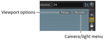
The view and cameras 
In Houdini, unlike in Maya, the view is usually independent of any camera object. However, you can link the view to a camera, and have the view keys move and rotate that camera.
| To... | Do this |
|---|---|
|
Match the view to a camera or light |
Click the camera menu in the viewport (to the right of the viewport options menu) and choose a camera or light to look through. Normally using the tumble keys after looking through a camera or light will switch the view back to “no cam” – by default the view has no connection to a camera/light. See the Note To prevent cameras from appearing in the viewport menu, add a spare parameter named |
|
Lock a camera view to prevent tumbling |
Click the camera menu in the viewport (to the right of the viewport options menu) and choose Lock Camera/Light Tumbling. Tip You can instead This parameter locks the current camera and light so they don’t adjust when you change the view. This turns off tumbling, but you can turn on Allow 2D Pan & Zoom when you still want to 2D pan and zoom in the viewport. |
|
Click the camera menu in the viewport (to the right of the viewport options menu) and choose Pin Current Camera. You can also use the ⇧ Shift + \ hotkey. This parameter pins your current camera so it stays in the camera menu regardless of the viewer’s current network. |
|
|
Use the view keys to position a camera or light |
Normally the Houdini viewer is set to “no cam”, meaning it’s not looking through any camera or light. When you choose a camera or light from the camera menu, the viewer switches to look through that camera/light, but if you use the tumble/track/dolly controls to change the view, the viewer switches back to “no cam”. Using the view keys to change the view does not normally move a camera or light. To use the view keys to move the camera or light you are looking through, you need to link the view to the camera/light.
or
Tip By default, the view is exported to the camera or light when the mouse button is released. This behavior can be overridden by turning on Export view continuously in the viewport camera menu. This option should be used with caution as exporting the view can trigger cooking. |
|
Create a new camera from the current view |
Click the camera menu and choose New camera, or Ctrl-click a camera or light icon on the shelf. See the sections on cameras and lights for more information. |
|
Switch between camera views |
Click the camera menu in the viewport (to the right of the viewport options menu) and choose Undo View/Redo View. You can also use the [ and ] hotkeys. This parameter switches between the latest and previous views. |
Camera path syntax 
Some nodes in Houdini let you reference camera paths. The following are the supported camera path formats.
LOP |
|
COP (layer) |
|
COP (geometry wire) |
For example, |
SOP (first output port) |
|
SOP (other output ports) |
For example, |
Note
0:0 is the default so you don’t need to include this part of the syntax when the COP or SOP has one output and one camera. For example, just enter /path/to/sop.
Viewport layout 
By default the scene view shows a single perspective view.
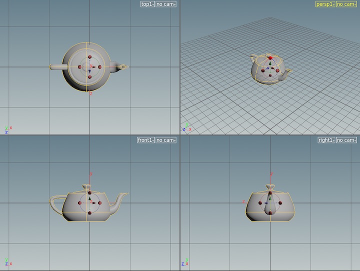
You can split the view into sub-views showing different view types, such as orthographic views or UV texture space. For example, you can switch to a quad-view showing top, side, front, and perspective views.
| To... | Do this |
|---|---|
|
Change the viewport layout |
By default the scene view shows a single perspective viewport. Click the |
|
Change the type of view in a viewport |
Click the Viewport options menu in the top-right corner of the viewport, and open the Set view submenu. Tip In the lower left of the viewport, click the gnomon axis to jump to the view facing that axis and re-click that axis to flip to the opposite side. X is left/right, Y is top/bottom, and Z is front/back.
|
|
Resize the viewports within a layout |
|
|
Set your layout sizes as the default |
To set your split sizes as the default for the current layout, do the following:
|
|
Temporarily maximize one viewport |
Move the mouse over the viewport and press Space + B. Press Space + B over the single viewport again to switch back to the multi-viewport layout.
|
|
Open a copy of a viewport in a floating window |
Click the Viewport options menu in the top-right corner of the viewport and choose Tear off Viewport Copy. A copy of the source viewport opens in a floating window. See Tear off viewport copy for more information. |
|
Make orthographic viewports pan and zoom together |
Open the |


Changing how Houdini displays the scene 
To change the shading mode, click the ![]() shading mode icon in the viewer’s toolbar.
shading mode icon in the viewer’s toolbar.
|
Wireframe bounding box |
Only draws a wireframe bounding box to represent geometry. |
|
Shaded bounding box |
Only draws a shaded bounding box to represent geometry. |
|
Wireframe |
Draws curves, surface isoparms, and polygon edges. |
|
Wireframe Ghost |
Like Wireframe, but ghosts (dims) lines obscured by surfaces. |
|
Hidden line invisible |
|
|
Hidden line ghost |
Like Hidden Line Invisible, but ghosts (dims) lines obscured by surfaces. |
|
MatCap shaded |
Uses a MatCap texture to define the shading of the surface, ignoring all other material assignments and scene lighting. |
|
MatCap wire shaded |
Like MatCap shaded, but also draws the wireframe over the shaded surfaces. |
|
Flat shaded |
Shades polygons but does not blend between them, making them appear faceted. |
|
Flat wire shaded |
Like flat shaded, but also draws the wireframe over the shaded surfaces. |
|
Smooth shaded |
Blends between shaded polygons making them appear smoother. |
|
Smooth wire shaded |
Like smooth shaded, but also draws the wireframe over the shaded surfaces. |
| To... | Do this |
|---|---|
|
Switch between wireframe and shaded mode |
Press W in the viewer. or
Open the viewport options menu and choose Shading ▸ Toggle wireframe/shaded. |
|
Open the full display options window |
Click the |
|
Hide the grid |
Click the |
|
Put an image in the background of a viewport |
(You can change “Disk file” to “COP image” to load the image from a compositing node instead.) |
Display toolbar 
The toolbar along the right side of the viewport has controls for what Houdini draws in the 3D viewer and how it draws the scene.
|
Show reference plane |
Draws a grid on the reference plane, that is the plane centered at the origin, perpendicular to the up direction (by default, the XZ plane). Right-click this button for a menu of options related to the reference plane grid. |
|
Show construction plane |
Displays the construction plane, which you can move and rotate to make it easier to draw, position, and snap along a plane. Right-click this button for a menu of construction plane options, such as showing the construction plane’s handle, allowing you to move and rotate it. |
|
Link Camera/Light to View |
If you are looking through a camera (or light) and turn this option on, moving the view using the tumble/track/dolly keys in the viewer will move and rotate the linked camera/light as well. |
|
Lock Camera/Light Tumbling |
If you are looking through a camera (or light) and turn this option on, this locks the current camera and light so they don’t adjust when you change the view. When on, you can turn on Allow 2D Pan & Zoom when you still want to 2D pan and zoom in the viewport. |
|
No Lights |
Don’t simulate lighting in the viewer. All surfaces are lit using a constant ambient light, with no shading. Right-click this button for a menu of lighting components to use (see Lighting for more information about these components). |
|
Work Lights |
Ignore lights that are in the scene and use one of the following work light setups:
Note All modes except Headlight can optionally cast shadows. Right-click this button to choose the work light mode and for a menu of lighting components to use (see Lights tab for more information about these components). Choose Properties from the drop-down menu for more configuration options. |
|
Scene Lights |
Shade the scene with more accurate approximation of the contributions from lights in the scene. Right-click this button for a menu of lighting components to use (see the Lights, Fog, and Camera tabs for more information about these components). |
|
Display materials |
Turn this on to show renderer approximations of materials in the viewer. Right-click this button for a menu of display and quality options. |
|
Object type visibility |
Click this button to show a menu of different object types to show/hide in the viewer. |
|
Object type visibility during playback |
This is a filter on what object types (currently visible in the object type visibility settings above) to show when animation is playing. Right-click this button to turn certain object types on or off. Click this button to turn the filter on or off. When the button is on, only object types turned on in the filter menu will appear during playback. (When the filter is on it also affects flipbook animations, but not a single-frame flipbook.) |
|
Points |
Draw small markers on points. |
|
Point normals |
Draw lines representing point normals. |
|
Point trails |
Draw lines visualizing each point’s velocity ( |
|
Point numbers |
Next to each point draw its number. |
|
Primitive normals |
Draw lines representing the face polygonal normals. |
|
Primitive numbers |
Next to each primitive (for example, polygonal face) draw its number. |
|
Hulls |
Draw hull wireframes for types such as NURBS and Bézier. Note For subdivision surfaces, turn this parameter on and off to switch between the subdivided surface and the original unsubdivided control cage. |
|
Tint backfacing polygons |
Tint the backfaces of polygons with a slight blue hue to indicate their orientation. |
|
Show UV texture when UVs present |
Show a UV visualization texture map on polygons when UVs are present on the geometry and no material is present. Right-click this button to open a menu of different texture maps to apply. |
|
Display 3D island boundaries |
Highlight the outer edges of a mesh that’s connected with shared points (that is, edges of the 3D island). |
|
Display UV island boundaries |
Highlight the outer edges of UV islands within a mesh. |
|
Particle origins |
Draw small axes on particles to show their orientation. |
|
Show group list |
Shows or hides the group list box in the viewer. |
|
Display background |
If you set up viewport background image(s) in the display options, use this button to show or hide the background images. |
|
Visualization |
Right click this icon to show the visualizer menu. Click this button to globally show or hide all active visualizers. |
|
Viewport messages |
Press and hold on this button to show messages/statistics generated for the current view. |
|
Apply to all split views |
When the viewer is split into sub-viewports, click this button to switch between the toolbar affecting all viewports, or just the current viewport (usually the last viewport you clicked in). |
|
Display options |
Show the display options window. |
Resetting the view 
Homing means to reset the view, either to a default view looking at the origin. You can also home to show all objects in the scene, or to show the selected objects. This is similar to the “zoom to fit” functionality in 2D illustration programs, PDF and image viewers, and so on.
Homing and framing controls are located in the viewport options menu (the left menu in the top right corner of viewports). This menu contains commands for homing the view, and lets you customize the default home view. For most homing functions, you’ll want to use the hotkeys.
To |
Viewport menu |
Hotkey |
|---|---|---|
Zoom to fit all objects |
Home ▸ Home All |
⇧ Shift + A |
Zoom to fit the selected objects |
Home ▸ Home Selected |
Space + G or Space + F |
Zoom to fit the grid |
Home ▸ Home Grid |
Space + H |
| To... | Do this |
|---|---|
|
Change the home view to a look along an axis |
Open the viewport options menu, click Home, then choose a view direction (along the X-axis, Y-axis, or Z-axis). |
|
Change the home view to look along a custom direction |
|
Showing other objects at the geometry level 
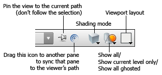
When you're editing inside an object, you can choose how/whether Houdini shows other objects in the scene using the ![]() Show All Objects/Ghost Other Objects/Hide Other Objects menu.
Show All Objects/Ghost Other Objects/Hide Other Objects menu.
|
Ghost Other Objects |
Other objects/levels appear “ghosted” (semi-transparent). This is the default. |
|
Show All Objects |
Show other objects and levels normally. |
|
Hide Other Objects (Local Space) |
Only show the geometry at the level you're working and hide others. This is in local space and removes object level transforms. |
|
Hide Other Objects (World Space) |
Only show the geometry at the level you're working and hide others. This is in world space and shows object level transforms. |
Setting display options for various levels/states 
You can set up different feature display and shading options for all geometry, selected geometry, geometry near the mouse pointer, and other states. For example, you can only show point numbers on points near the mouse pointer, or only on selected geometry, to avoid cluttering the display.
-
Click the
display options button to the right of the viewer, or press D over the viewer. -
Click the Markers tab.
-
Choose the state you want to change from the Set display options for menu.
This menu controls what category of geometry the options below apply to.
Scene Geometry
Display options for unselected objects at the object level look like.
Selected Scene Geometry
Display options for selected objects at the object level. By default this is the same as “Scene geometry”.
Ghost Scene Geometry
When you are at the geometry level (inside a Geometry object), you can optionally show other objects “ghosted” (semi-transparent). This shows display options for these ghosted objects.
Display Model Geometry
At the geometry level (inside a Geometry object), display options for the output of the node with the display flag.
Current Model Geometry
Display options for the selected geometry node’s output. At the geometry level, when you select a node that doesn’t have the display flag, the view shows the output of the selected node (by default, as wireframe) along with the output of the network. This lets you edit the node and see the effects in the view.
Template Model Geometry
Display options for “templated” geometry. You can set the
 template flag on a geometry node to keep the node’s output visible at the geometry level alongside the display geometry.
Note
The Use menu next to this menu might be set to use the settings from another state. You can set Use to “Unique settings” to give the chosen state its own settings.
-
Click the checkbox next to the features you want to be visible in this state.
Use the
 visibility icon menu to the right of each option to control when the given feature is visible (always, selected, near pointer, under pointer).
 -
In the rightmost column, choose the shading style and drawing options for geometry in the chosen state. For example, Ghosted draws the geometry semi-transparent, and Faded dims its colors to make it slightly less visible.
Color correcting the view 
To show the color correction toolbar, click the view dropdown menu (beside the camera menu) in the top right corner of the viewport and turn on Correction Toolbar. The toolbar can also be shown using the toggle in the ![]() menu on the
menu on the ![]() Display Options button, at the bottom of the right viewport toolbar.
Display Options button, at the bottom of the right viewport toolbar.
See Color management in Houdini for more information.
Tear off viewport copy 
Click the Viewport options menu in the top-right corner of any viewport and choose Tear off Viewport Copy to open a copy of the viewport in a new floating window. The window copies the source viewport’s settings at the moment it’s torn off. The floating window is then its own viewport that you can tumble and move around in, with its own display options you can change (unless ![]() Apply to all split views is on).
Apply to all split views is on).
The viewport copy shares its resources with the source viewport from which it’s torn. Though this increases the speed of the floating window, the window also shares the following restrictions of the source viewport:
-
you can’t view networks different than the source’s network
-
you can’t be in a state different than the source’s state
-
some display options apply to all viewports in a viewer
Material display 
Materials can be assigned to geometry by dragging and dropping a material
from the Material Palette or
Network Editor onto object geometry. Materials can also be
assigned with a ![]() Material SOP or
Material Stylesheet.
Material SOP or
Material Stylesheet.
Material display can be disabled by clicking by ![]() Display Materials toggle on the right viewport toolbar. Finer control over material assignments and options, such as texture display, particle display, and transparency, can be found in its
Display Materials toggle on the right viewport toolbar. Finer control over material assignments and options, such as texture display, particle display, and transparency, can be found in its ![]() menu.
menu.