| On this page |
Grids 
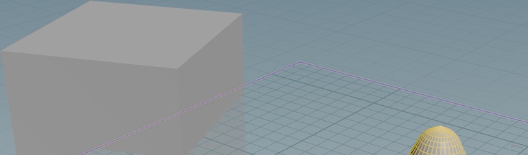
Houdini has two grids: the reference plane which helps you orient yourself in 3D space, and the construction plane which tools place things relative to.
Reference plane 
The default infinite XZ grid shown in the viewer is the reference plane.
| To... | Do this |
|---|---|
|
Show or hide the reference plane |
Click the |
|
Customize the reference plane grid |
Right-click the See the reference grid parameters below. Tip You can set the Ruler type directly from the right-click menu on the icon. |
Construction plane 
Many modeling operations, such as creating a new objects using the tools in the Create shelf tab and drawing curves, are relative to the construction plane.
The default construction plane is the same as the reference plane (an XZ grid centered on the origin).
You can change the display of the grid on the construction plane, or move/reorient the construction plane to make it easier to model in an area not centered on the origin, or in a space other than the XZ ground plane.
Tip
When you're using the construction plane, you might also want to turn off the ![]() reference plane to avoid confusion.
reference plane to avoid confusion.
| To... | Do this |
|---|---|
|
Show or hide the construction plane |
Click the |
|
Show or hide the construction plane handle |
The construction plane handle lets you position, rotate, and align the construction plane interactively in the viewer.
Tip The construction plane extends to infinity. However, you can resize the visual indication of the construction plane by dragging the handles at the corners.
|
|
Align the construction plane to geometry |
With construction plane handle shown (see above), click a component (face, edge, or point) to snap the construction plane to the component and align construction plane’s normal with the component’s normal.
Tip You can quickly align the construction plane as you work using the sticky construction plane handle key. For example, press and hold /, click a face to align the construction plane to it, then release the key. |
|
Set the construction plane perpendicular to the current viewing direction |
Right-click the |
|
Customize the construction plane grid |
Right-click the |
|
Return the construction plane to the default |
Right-click the |


Grid parameters 
Grid spacing
How far apart (in Houdini units) to draw the grid lines.
Grid ruler
Show numbers on the axes at these intervals. For example, 5 means show numbers on the grid at 5, 10, 15, and so on. See also the Ruler type option below.
Origin
Center the grid plane around this point (in world units). An easier way to position the construction plane is to use its handle (see above).
Rotation
Specifies the orientation of the grid plane.
Ruler type
No ruler
Don’t show numbers on the grid.
Ruler on main axis
Show numbers on the vertical and horizontal axes.
Ruler on grid points
Show numbers across the entire grid.
Quick-views and quick-planes 
Similar to quickmarks in the network editor, you can store and recall a few commonly-used views, and a few construction planes, and switch between them easily using hotkeys.
| To... | Do this |
|---|---|
|
Save a view |
Hold Space to enter the view tool, then press ⌃ Ctrl and 6, 7, 8, or 9. (On Mac, press ⌘ and 6, 7, 8, or 9.) |
|
Return to a quick view |
Hold Space to enter the view tool, then press 6, 7, 8, or 9. |
|
Save a construction plane |
Tap / to enter theconstruction plane state, then press ⌃ Ctrl and 6, 7, 8, or 9. (On Mac, press ⌘ and 6, 7, 8, or 9.) |
|
Return to a construction plane |
Hold / to enter the construction plane state, then press 6, 7, 8, or 9. |
Note
Saving a quick view saves everything about the view at that moment, including display options such as whether points are displayed, what guides are visible, and the shading mode.
Snapping 
Use the ![]() Enable Snapping button in the toolbox (on the left side of the viewer pane) to turn snapping on and off.
Enable Snapping button in the toolbox (on the left side of the viewer pane) to turn snapping on and off. ![]() the
the ![]() Enable Snapping button to see a menu of options.
Enable Snapping button to see a menu of options.
Once snapping is on, choose one of the following snap options in the toolbox.
![]() Grid Snapping
Grid Snapping
Snap to points on the construction plane.
![]() Primitive Snapping
Primitive Snapping
Snap to curves and edges.
![]() Point Snapping
Point Snapping
Snaps to points.
![]() Multi-Snapping
Multi-Snapping
Snap to different things simultaneously. ![]() the
the ![]() Enable Snapping button and choose Snapping Options to set priorities for individual types of snapping.
Enable Snapping button and choose Snapping Options to set priorities for individual types of snapping.
Options menu 
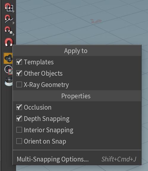
Snapping Options
Open the Snap options window for more snapping settings to configure. The other menu options also appear in the Snap Options window.
Current Geometry
At the Geometry level, you can snap to the ![]() visible geometry (geometry of the current node).
visible geometry (geometry of the current node).
Templates
At the Geometry level, you can snap to ![]() templated geometry (geometry that is made visible for reference purposes, using the template flag).
templated geometry (geometry that is made visible for reference purposes, using the template flag).
Other Objects
At the Geometry level, you can snap to geometry from other objects, not just the object you are inside.
Guides
At the Geometry level, you can snap to guided geometry (geometry that appears only when your state is active).
X-Ray Geometry
At the Object level, you can snap to geometry in objects with the X-ray flag set.
Occlusion
Prevents snapping to geometry hidden (occluded) behind shaded surfaces. When Occlusion is on, you can only snap to visible geometry.
Depth Snapping
If you turn this option off, you can snap to reference geometry. When the only constraint applied to a motion is the plane (construction or view), the point stays at its current elevation relative to the plane.
Tangent Plan Snapping
Snap to the intersection of the line and the plane tangent to the primitive under the cursor when dragging along a line rather than directly to the primitive itself.
Interior snapping
Snap to the midline of enclosing geometry under the cursor. Click View Based or Normal Based to set how the center of the target geometry is chosen.
Orient on Snap
When you snap one object to another, normally the orientation of the object remains the same and only its location changes. If this option is turned on, the object rotates according to the preference set in the snapping options window. The default is to rotate so the closest major axis (x, y, z) points in the direction of the thing you are snapping to.
Align handles to geometry 
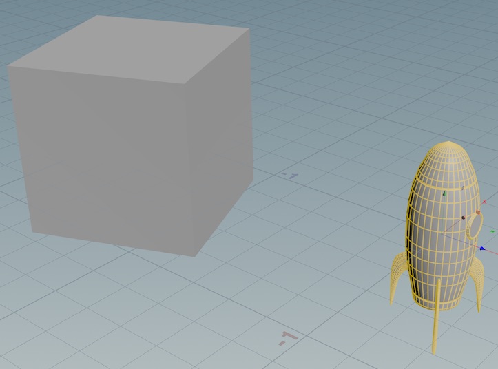
In many Houdini tools, viewer handles let you interactively edit parameter values in the viewer, such as the Transform and Rotate handles that let you position and rotate objects.
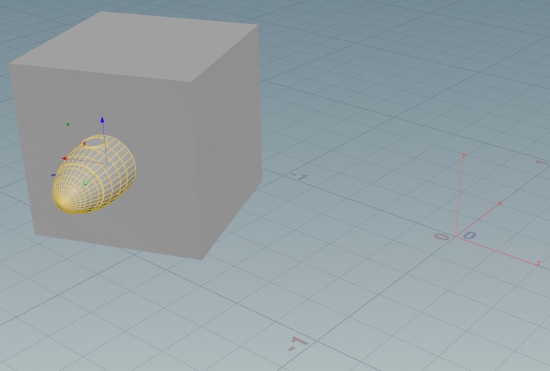
Often you want to position and/or rotate those handles based on existing geometry. For example, you might want to position a cube object’s pivot at one of its corners. You can use the alignment state/hotkey to align handles with geometry.
Tip
The ![]() Align Components shelf tool provides a higher-level workflow for aligning geometry to geometry.
Align Components shelf tool provides a higher-level workflow for aligning geometry to geometry.
| To... | Do this | ||||||||
|---|---|---|---|---|---|---|---|---|---|
|
Switch to align state |
Do one of the following:
Unless you hold the key, once you align the handle Houdini will automatically exit the align state. |
||||||||
|
Align a handle to geometry |
You can align a handle to the position and/or normal of a face, edge, or point.
|
||||||||
|
Set the alignment axis |
By default, Houdini aligns along the “up” axis (+Y in the default settings). You can set a primary axis to control which axis Houdini uses when you align the handle to geometry.
|
||||||||
|
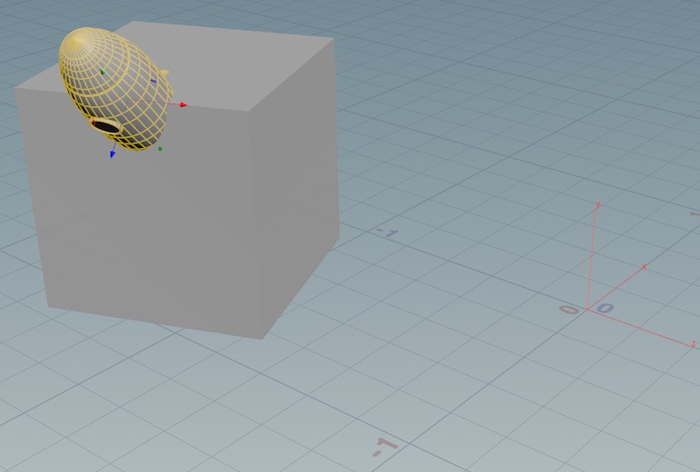
Orient the handle based on geometry |
This procedure orients the handle based on some existing geometry. It does not move the handle.
|
||||||||
|
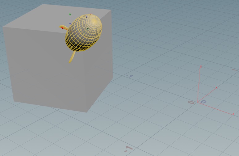
Do secondary orienation |
After you orient the handle along one axis (see above), you can “lock” that axis orientation and try to orient the other two axes based on other geometry. Tip This procedure involves multiple steps in the handle align state. If you enter the align state using the context menu or by tapping the key, the state will end after the do the primary orientation, and you will need to re-enter the state to do the secondary orientation. Or, you can perform both orientation steps while holding the state key.
Note It may not always be possible to accomplish the secondary orientation if it conflicts with the locked primary axis orientation. |
||||||||
|
Align a handle with the construction plane |
Right click the handle and choose Align handle ▸ C-plane axes. |