| On this page |
Constraint networks 
The ![]() RBD Material Fracture tool not only fractures your geometry, but it also creates constraints for you between those pieces. If you want to create more constraints, there are 3 SOPs that allow you to do so, separate from the fracturing process. They follow the same 3 input/3 output RBD workflow, and give you a lot of control for building constraints. This is useful when you're fracturing two different types of materials, and want to create boundary constraints between them.
RBD Material Fracture tool not only fractures your geometry, but it also creates constraints for you between those pieces. If you want to create more constraints, there are 3 SOPs that allow you to do so, separate from the fracturing process. They follow the same 3 input/3 output RBD workflow, and give you a lot of control for building constraints. This is useful when you're fracturing two different types of materials, and want to create boundary constraints between them.
Tip
The constraint nodes provide a HUD with shortcuts and information about how to create constraints between pieces. In the viewport, hit Enter to activate the draw/edit mode. Then, press ⇧ Shift + F1 to display the HUD.
Tip
Sometimes, pieces aren’t accessible, because they're located inside an object and occluded by other fragments. To access those occluded pieces, turn on Geometry Culling. Then, move the mouse to the viewport and press 5 to display a customizable bounding box. Everything outside the box will be culled.
This node allows you to create and edit constraints between pieces in the viewport. It allows you to interactively draw constraints between the pieces you want to be connected. Once the constraint is drawn, you can choose the Connection Type to determine how the constraints are set up. For more information, see the ![]() RBD Constraints From Lines help page.
RBD Constraints From Lines help page.
This tool lets you draw a curve in the viewport, and will create constraints between points on the geometry of nearby pieces within a specified search radius. RBD Constraints from Curves also gives you the option to provide a curve in the 4th input, so that you can use it procedurally. For more information, see the ![]() RBD Constraints From Curves help page.
RBD Constraints From Curves help page.
This tool is a procedural node for creating constraints based on a set of rules and conditions. For example, you can constrain pieces based on groups and then only constrain the pieces that are within a certain bounding region.
All three constraint nodes will create simple primitives with a rest length attribute. The ![]() RBD Constraint Properties SOP node can be used afterward to create constraint groups and set up constraint types (such as glue or soft constraints). The help for the
RBD Constraint Properties SOP node can be used afterward to create constraint groups and set up constraint types (such as glue or soft constraints). The help for the ![]() Constraint Network DOP has more background information about constraint networks (Constraint Network is the low-level DOP node responsible for converting SOP constraint geometry into the equivalent DOP constraints).
Constraint Network DOP has more background information about constraint networks (Constraint Network is the low-level DOP node responsible for converting SOP constraint geometry into the equivalent DOP constraints).
Types of connections 
All three constraint nodes (![]() RBD Constraints From Lines,
RBD Constraints From Lines, ![]() RBD Constraints From Curves, and
RBD Constraints From Curves, and ![]() RBD Constraints From Rules) will let you choose between the following types of connections.
RBD Constraints From Rules) will let you choose between the following types of connections.
|
The default connection that’s created is Hinges. These create a hinge-like constraint between pieces, which you can visualize by the white dot on the constraint line. |
|
Drawing Surface Points constraints will create anchor points where you clicked the mouse on the piece to place the constraint. |
|
Center of Mass constraints will calculate the center of mass for the constrained pieces and create constraints between their centroids. |

RBD Convert Constraints 
The ![]() RBD Convert Constraints SOP allows you to easily take your existing constraints and convert them into a different type of constraint. The Constraint Type dropdown menu lets you decide if you want your constraints to be from the Center of Mass, Surface Points, or Faces.
RBD Convert Constraints SOP allows you to easily take your existing constraints and convert them into a different type of constraint. The Constraint Type dropdown menu lets you decide if you want your constraints to be from the Center of Mass, Surface Points, or Faces.
Tip
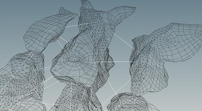
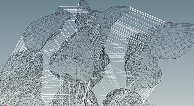
Use the ![]() RBD Exploded View SOP to better visualize how your constraints are connected between the pieces.
RBD Exploded View SOP to better visualize how your constraints are connected between the pieces.
Center of Mass
Surface Points
Faces
For more information, see the ![]() RBD Convert Constraints SOP help page.
RBD Convert Constraints SOP help page.
Cone twist constraint properties 
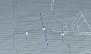
The ![]() RBD Cone Twist Constraint Properties SOP allows you to edit constraints interactively in the viewport, by either directly editing the global parameters on the node itself, or by making individual edits to the constraint’s attributes. This node gives you many advanced options such as specifying rotation limits, twist axes, and translation ranges.
RBD Cone Twist Constraint Properties SOP allows you to edit constraints interactively in the viewport, by either directly editing the global parameters on the node itself, or by making individual edits to the constraint’s attributes. This node gives you many advanced options such as specifying rotation limits, twist axes, and translation ranges.
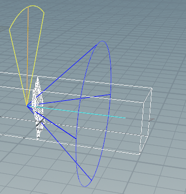
You can set angle ranges for the amount of twisting allowed around the primary axis, as well as the rotation limit within the cone. These axes are aligned for the constrained and goal objects, because in most cases they will be the same. You can manually edit individual constraints in the viewport, or select multiple and have the same edits applied to all of them.
The light blue line represents the constrained object’s twist axis, which can swing around anywhere within the dark blue cone (rotation boundary). The yellow boundary represents how much twist is permitted around the axis.
| To... | Do this |
|---|---|
|
Soften the boundary when an object hits the edge of the cone. |
Decrease the Angular Limit Stiffness parameter to allow the object to swing more freely before bouncing back. |
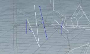
You can also set Translation Limits to allow the pieces to stretch apart from each other, within a set limit. By default, the translation limits are set to 0, but after you set a limit, you will see a visual representation in the viewport. For example, if you enable translation along the twist axis, you will see 2 squares in the viewport to illustrate how far the anchor points can move away from each other. This is useful for mechanical setups, such as simulating pistons or the suspension system on a car.
![]()
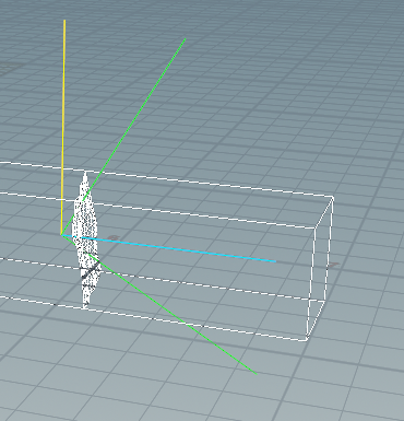
Translation can be done along all 3 axes. If two are set, you will see a planar representation in the viewport, and if all three are set, you will see a box within which the constraint can move.
![]()
![]()
Tip
You can Disable Collisions between the pair of objects that are constrained if they are very close together. This will give you more motion, as the collisions won’t be getting in the way of the rotation and translation constraints. This could also eliminate jittery behavior.
| To... | Do this |
|---|---|
|
Soften the boundary when an object hits the edge of a translation limit. |
Decrease the Position Limit Stiffness parameter to soften the boundary and make it more bouncy. |
The Motor parameters give you to option to set a specific target rotation and target position for the object to try to get to. The motor is represented by green lines in the viewport, and is what the constraints will pull toward.
Tip
The Target Current Pose option lets you use whatever the current position is as the new rest state, which is useful for plasticity. It makes the objects try to stay at the current orientation at every frame. This also prevents the objects from trying to spring/snap back.
| To... | Do this |
|---|---|
|
Select all constraints |
Press ⌃ Ctrl + A in the viewport. |
|
Use the handles in the viewport to adjust the values in the parameter editor and apply them to all of the constraints |
Turn on the Edit Parms checkbox in the toolbar. This will apply the changes to all constraints that don’t have any manual edits. You can also turn this on by pressing P in the viewport. |
|
Clear all manual edits |
Click the Clear Edits button in the toolbar or in the parameter editor. |
|
Reset the constraint you are currently editing to its default value |
Press U in the viewport This works like an “undo” option. |
|
Reset the motor you are currently editing to its default value |
Press I in the viewport. This works like an “undo” option. |
|
Copy and paste constraint limits |
|
|
Activate the Motor parameters |
Press O in the viewport to toggle on the motor parameters. This is the same as turning on the Motor checkbox in the parameter editor. |
|
Add resistant to rotation (so it doesn’t rotate too fast) |
Turn on Enable Motor and Target Current Pose. This will try to maintain the current relative orientation depending on the motor’s strength. |
|
Lock the Axis |
Press L in the viewport. By default there is a symmetrical rotation range, and when you edit a rotation limit, the change is made on both sides of the axis. Turning on Axis Lock will keep one side of the limit frozen and only change the other side. It will also move the axis so that it is in the center of the angle. |
|
Dampen the motion toward the edge of the limit |
The Softness parameter starts affecting the motion before reaching the rotation limit, so it can damp the motion while you're still within the rotation range. Unlike Angular Limit Stiffness, which is applied after exceeding the rotation limits and doesn’t damp the motion within the rotation range. |
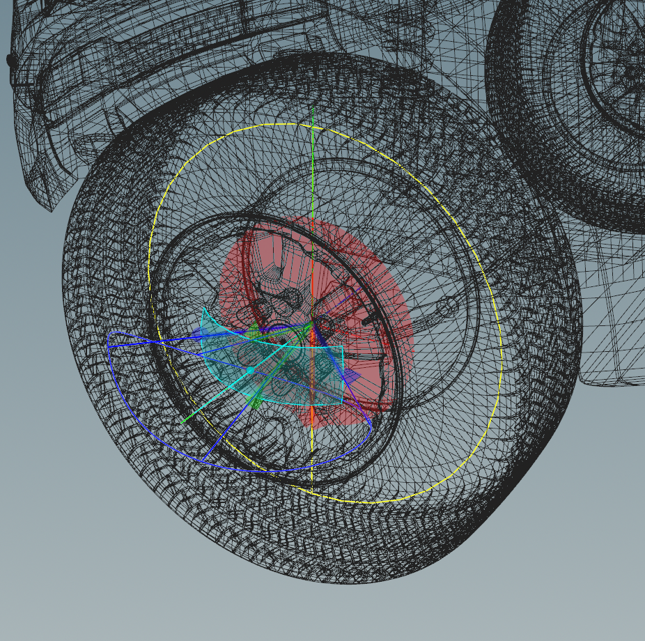
Controlling constraint behavior 
The ![]() RBD Bullet Solver node has parameters on the Constraints tab that let you control the behavior of constraints. The Breaking Thresholds subtab allows you to determine when to break constraints apart. For example, you can use the Distance Threshold to set the distance between anchor points beyond which a constraint will break, or the Force Threshold to set the force beyond which a constraint will break.
RBD Bullet Solver node has parameters on the Constraints tab that let you control the behavior of constraints. The Breaking Thresholds subtab allows you to determine when to break constraints apart. For example, you can use the Distance Threshold to set the distance between anchor points beyond which a constraint will break, or the Force Threshold to set the force beyond which a constraint will break.
Note
Turning on the constraint color visualizations can help determine which breaking threshold to use, and also help with debugging.
The ![]() RBD Constraint Properties node provides functionality similar to the parameters on the
RBD Constraint Properties node provides functionality similar to the parameters on the ![]() RBD Material Fracture node’s Constraints tab. You can use this as a convenient interface to edit values in the constraint network if you want to do more complex custom constraints. There are parameters to control plasticity in terms of stretching as well as the angle between the two objects in degrees where plasticity starts to take effect. This is useful for bending and breaking effects, where you want things to bend and hold their shape. For more information, see Bending and breaking.
RBD Material Fracture node’s Constraints tab. You can use this as a convenient interface to edit values in the constraint network if you want to do more complex custom constraints. There are parameters to control plasticity in terms of stretching as well as the angle between the two objects in degrees where plasticity starts to take effect. This is useful for bending and breaking effects, where you want things to bend and hold their shape. For more information, see Bending and breaking.
Tip
The Use Tags parameter on the RBD Material Fracture SOP, creates a constraint_tag string attribute on the constraint primitives instead of using primitive groups. This allows for more flexibility and matches the Vellum constraints. Tags can also be used with the Constraint Group parameter on the RBD Constraint Properties SOP to easily alter specific constraints.
Constraint browser pane 
The Constraint Browser allows you to visualize and manage the attributes of existing RBD and Vellum constraints. For more information, see the Constraint Browser help page.
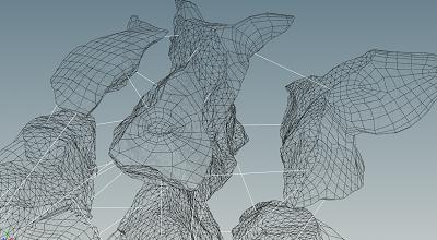
Understanding constraint networks 
Houdini lets you set up constraints in SOPs using constraint geometry. This is a set of polylines with attributes that represent constraint relationships between geometry pieces. These are translated into the equivalent DOP constraints when the geometry is imported into the DOP network. This is to make it easy to set up, edit, and visualize constraints using the large number of SOP nodes dedicated to editing geometry and attributes.
-
Each constraint is represented by a two-point polyline.
-
Each polyline has a
constraint_typeprimitive attribute specifying the constraint type. The two common RBD constraint types areglueandsoftconstraints.Glue constraints keep two pieces together until the amount of force trying to separate them is greater than the glue strength.
Soft constraints are similar to springs, but instead of being bouncy, they bend until they break.
-
The polyline can have additional primitive attributes related to the constraint, such as
strengthfor glue, orstiffnessanddampeningfor soft constraints. -
The two endpoints each have a
nameattribute specifying the name of the piece that end represents. -
The position of the endpoints may be used by different constraints, for example as anchor points.
Pre-constraining pieces 
If you have multiple connected pieces you want to fracture in different ways, you can optionally use the ![]() RBD Constraints From Rules node before you use
RBD Constraints From Rules node before you use ![]() RBD Material Fracture to break them up.
RBD Material Fracture to break them up.
For example, if you are destroying a house, you can start by constraining the door and windows to the walls they're embedded in.
As the RBD Material Fracture node breaks up the individual objects, it tries to intelligently update existing constraints. For example, if a pane of window glass starts constrained to the surrounding window frame, even as RBD Material Fracture shatters the glass, the node will keep the outer shards attached to the frame.