| On this page |
The high-level tool for pre-fracturing geometry is the ![]() RBD Material Fracture SOP, which allows you to accurately fracture geometry based on a specific type of material. Custom material types are more advanced than the preset concrete, glass, and wood types. It’s a way of bridging the gap between doing your own fracturing and using the presets. This option lets you use your own cutting planes, but still take advantage of all the controls the
RBD Material Fracture SOP, which allows you to accurately fracture geometry based on a specific type of material. Custom material types are more advanced than the preset concrete, glass, and wood types. It’s a way of bridging the gap between doing your own fracturing and using the presets. This option lets you use your own cutting planes, but still take advantage of all the controls the ![]() RBD Material Fracture SOP node has to offer, such as edge detail, interior detail, constraint creation, and rewiring. It also exposes the boolean “treat as” parameter for solid or surface cuts which can be useful for metal fracturing.
RBD Material Fracture SOP node has to offer, such as edge detail, interior detail, constraint creation, and rewiring. It also exposes the boolean “treat as” parameter for solid or surface cuts which can be useful for metal fracturing.
Note
Fracture per Piece is useful to target specific custom cutters to specific pieces. If a name primitive attribute is found on the cutting geo, only the cutting geo with a matching name will be used to cut the pieces being fractured.
| To... | Do this |
|---|---|
|
Visualize the guides for the cutter geometry |
Choose Custom from the Material Type dropdown menu on the
|
|
Control how many cutting planes are created |
Increase or decrease the Scatter Points parameter to add or remove the number of default cutting planes that are created. By default the
|
|
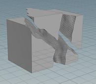
Add more noise to the cuts |
Turn on Edge Detail.
|
|
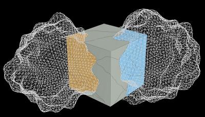
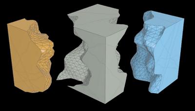
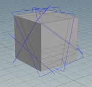
Use your own cutting plane |
Turn off the Scatter Cutting Geo checkbox, wire in your own geometry to the 4th input of the node, and turn on the Input Cutting Geo checkbox. Note You can wire in multiple cutting planes to the 4th input. |
|
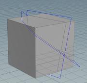
Draw exactly where the fracture will be |
Use the |
Understanding Chipping parameters 
The chipping parameters can give you a lot of control over the look of the chipped pieces.
| To... | Do this |
|---|---|
|
Control how many pieces get chipping applied |
Increase or decrease the Chipping Ratio parameter. A value of |
|
Determine how many of the corners get chipping applied |
Adjust the Corner Ratio. A value of |
|
Regulate how big the chips are |
Modify the Corner Depth parameter to control how big the chips will be relative to the center of the piece. Increasing this parameter will make the chips bigger. |
|
Provide variation in cutting planes |
Use the Directional Noise parameter. A value of |
|
Control how strongly the chipped pieces stick to the main fracture piece. |
Modify the Chipping Glue Strength on the Constraints tab. |
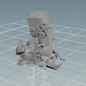
Example: Using geometry as a custom cutter 
-
Create a
 Box at the origin using the tool on the Create shelf.
 -
Dive down to the geometry level and increase the Size in the Y direction to
4. -
Move it up so that it’s sitting flush on the ground plane by increasing the Y value of the Center parameter to
2. -
Append an
 RBD Material Fracture SOP to the first input of the box.
The default Material Type is Concrete (voronoi fracture). In this example, we’ll be using a bunch of spheres to cut up the geometry.
-
Create an
 ISO Offset SOP and wire the box into its first input. This will create a volume for copying the spheres.
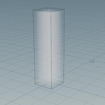
-
Set the Uniform Sampling Divs to
100. -
Append a
 Scatter SOP after the ISO Offset node and change the Force Total Count to
 25to scatter a few points inside the geometry. -
Append an
 Attribute Randomize SOP after the Scatter node.
 -
Set the Attribute Name to
pscale, change the Dimensions to a value of1, set the Min Value to0.5and the Max Value to2. This will randomize thepscaleattribute, which controls the scale of the spheres that will be copied onto the points. They will vary between a size of0.5and2. -
Create a
 Sphere SOP, change the Primitive Type to Polygon, set the Frequency to
 8, and reduce the Uniform Scale to0.5. -
Create a
 Copy to Points SOP and wire the sphere into the first input and the attribute randomize node into the second input.
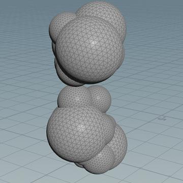
-
Wire the output of the copy to points node to the last input of the RBD Material Fracture node. This will allow the spheres to be used as the cutting geometry for the box.
-
On the
RBD Material Fracture SOP, change the Material Type to Custom, set the Guide Geometry to Cutter Geometry, turn off the Scatter Cutting Geo checkbox, and turn on the Input Cutting Geo checkbox. You should see the spherical guide cuts in your geometry.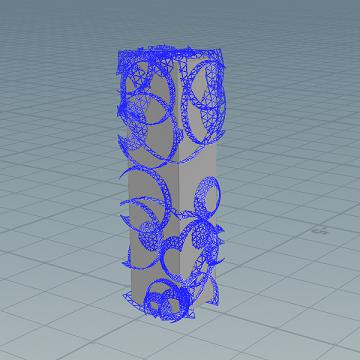
-
On the Constraints tab, set the Primary Strength to
200. -
Append an
 RBD Bullet Solver SOP to the RBD Material Fracture SOP.
 -
On the Ground tab, change the Add Ground Plane dropdown from None to Ground Plane.
-
Press
 in the playbar to play the simulation.