Guided simulations use the motion of the pieces from an existing simulation to drive the motion of the pieces in a higher resolution simulation. You can create guided simulations by turning on Use Guides on the Guided Simulation tab of the ![]() RBD Bullet Solver SOP, and wire the output of your guided simulation in the 5th input. This will cause the solver to look for nearby pieces and keep the same velocity and overall motion until they collide with other things and break apart.
RBD Bullet Solver SOP, and wire the output of your guided simulation in the 5th input. This will cause the solver to look for nearby pieces and keep the same velocity and overall motion until they collide with other things and break apart.
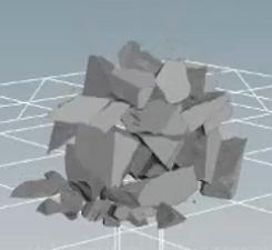
Low-res fracture
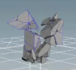
High-res fracture
Note
There is a Show Guided (Blue) option on the Visualization tab of the solver, which is very useful for seeing which pieces are still being controlled by the guided simulation.
Low-res simulation
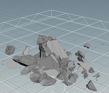
High-res simulation
Guided simulation
On the Guide tab of the ![]() RBD Bullet Solver SOP there’s a few setup options such as which Guide Method you want to use. There are also Release Threshold parameters, which let you decide when to stop having a piece guided. Typically this is based on linear and angular velocity.
RBD Bullet Solver SOP there’s a few setup options such as which Guide Method you want to use. There are also Release Threshold parameters, which let you decide when to stop having a piece guided. Typically this is based on linear and angular velocity.
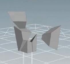
The 5th input doesn’t necessarily have to be a simulation. You could alternatively animate the general motion you want the pieces to follow. The following example uses a ![]() Bend SOP to make the pieces split in opposite directions.
Bend SOP to make the pieces split in opposite directions.
To achieve full control over guided simulations, you can add an upstream RBD Guide Setup node. There you can find all relevant parameters, for example which frame range you want to use or how neighbors are included. You can also see a Use VEXpression dialog if you want to control over the guide strength in custom ways.
Note
In this example, a RBD Guide Setup node will not be used and all settings are made in the solver. Go to the solver’s Advanced tab and turn off Use Pre-Configured Setup.
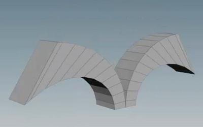
Animated geometry
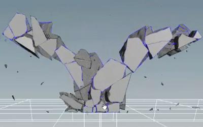
Guided simulation
Example: Setting up a simple guided simulation 
-
Create a
 Box at the origin using the tool on the Create shelf.
 -
Dive down to the geometry level and increase the Size in the Y direction to
4. -
Move it up so that it’s sitting flush on the ground plane by increasing the Y value of the Center parameter to
2. -
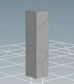
Append an
 RBD Material Fracture SOP to the first input of the box.
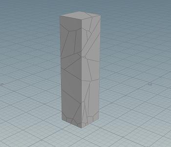
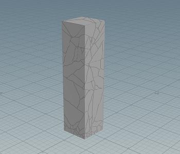
-
Create additional fractures by clicking the + in the Fracture Level parameter. This should bring your value to
3. -
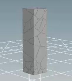
On the Chipping tab, turn on Enable Chipping. This will create realistic small chipped pieces on the corners of the fractured pieces.
-
On the Details tab, turn on Edge Detail to add more noise to the cuts, making them appear more jagged along the edges.
-
Turn on Interior Detail as well, to add noise and displacement to exposed interior surfaces after fracturing.
Note
The second input and output on the
RBD Material Fracture SOP are constraints. These are glue constraints that control how strongly the fractured pieces hold together. On the Constraints tab, the Primary Strength parameter controls how strongly the main fractured pieces hold together and the Chipping Glue Strength controls how strongly the chipped pieces stick to the main fracture pieces. -
On the Constraints tab, change the Primary Strength to
100and the Chipping Glue Strength to50to allow the pieces to break apart more easily. -
Append an
 RBD Bullet Solver SOP, and wire the first 3 inputs to the 3 outputs of the RBD Material Fracture SOP.
 -
On the Collision tab, change the Ground Type dropdown from None to Ground Plane.
-
Create a
 Bend SOP, wire the first input to first output of the RBD Material Fracture SOP, and wire the output to the 5th input of the RBD Bullet Solver SOP.
 -
Change the Capture Direction to be in the Y direction by changing the Y parameter value to
1, and Z to0. -
Change the Capture Length to
4, since the box is 4 units long. -
Disable the bend by turning off the Enable checkbox in the Bend section, and enable the twist by turning on the Enable checkbox in the Twist section.
-
In Twist parameter, use the expression
$FF*3. This is the current frame number($FF) multiplied by a value of3.If you press
 in the playbar, you will see the twisting motion deforming the pillar.
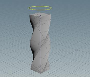
-
On the Guide tab of the
RBD Bullet Solver SOP, turn on the Enable Guides checkbox.If you press
again, you will see some unusual breaking behavior. You will need to tweak a few more values to get better crumbling results. -
On the Guide tab, reduce the Blend value to
0.7. This parameter blends in how strongly the guide geometry effects the behavior of the pieces. A value of 1 means the guide geometry has full control. -
In the Release Thresholds section, turn off the Linear Threshold and Angular Threshold parameters. This disables the internal constraints created by the Bullet Solver, which pin the simulation geometry to the guide geometry.
-
In the Accumulated section, turn on the Distance Threshold parameter and set the value to
0.15. This will break the constraints once the pieces have an accumulated distance of0.15past their original position. -
Navigate to the Advanced tab and turn on the Guided Neighbors checkbox.
-
On the Guided Neighbors section, turn on the Ensure Neighbor checkbox. This will check for each piece if neighboring pieces have already been disconnected from the guided sim. If they have been, the piece will also disconnect.
-
Press
in the playbar to start the simulation.