| On this page |
There are several ways to fracture geometry using various shelf tools. For example, you can cut up geometry by using the ![]()
![]() Shatter tool tool on the Model tab of the shelf, or fracture a dynamic object by using the
Shatter tool tool on the Model tab of the shelf, or fracture a dynamic object by using the ![]()
![]() RBD Fractured Object tool on the Rigid Bodies tab of the shelf. You can also dynamically smash an object by using the
RBD Fractured Object tool on the Rigid Bodies tab of the shelf. You can also dynamically smash an object by using the ![]()
![]() Make Breakable tool on the Rigid Bodies tab of the shelf.
Make Breakable tool on the Rigid Bodies tab of the shelf.
Shelf tools always create a DOP-based setup. There, all geometry is stored inside a ![]() Geometry OBJ, while the dynamic network is located inside a
Geometry OBJ, while the dynamic network is located inside a ![]() DOP Network OBJ. The Shatter shelf tool is an exception, because it only creates a fracture geometry network without dynamics. For information on how to work with the shelf tools, please visit Shattering.
DOP Network OBJ. The Shatter shelf tool is an exception, because it only creates a fracture geometry network without dynamics. For information on how to work with the shelf tools, please visit Shattering.
Voronoi-based methods are based on points. Each point marks the center of a fragment and ideally, the number of points also defines the number of pieces.
One of Houdini’s long-term aims is to move workflows from DOPs to SOPs for a more user-friendly workflow. SOP-based fracture setups offer a wide variety of possibilities and methods:
-
The most flexible approach uses the all-in-one
 RBD Material Fracture SOP node. This node lets you choose from different fracture modes like concrete or glass. You can also add Voronoi points, multiple fracture levels, chips and edge detail directly inside the node. Furthermore it’s possible to make all relevant constraints settings in one node. If you need more control over points and constraints, you can use separate nodes instead of the node’s built-in features.
 -
Alternatively, you can create your scenes through more “traditional” workflows, for example with
 Voronoi Fracture SOP or
  Boolean Fracture SOP nodes. Here, Voronoi scatter points and constraints are managed through specific nodes. Extras, like edge and surface detail, require custom networks.
Import Geometry 
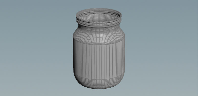
No matter which method you finally use, the first step is to import the geometry you want to break apart.
-
On the Network Editor’s obj level, press ⇥ Tab to invoke the TAB menu. From there, create a Geometry OBJ. Double click the node to dive into it.
-
Load geometry into the Houdini SOP geometry environment, e.g. through a
 File SOP. Make sure all file operations use
 $HIPas you will need to reference the file if using a render farm for the final simulation.
Note
Analyze the geometry prior to fracturing, make sure all points on the geometry are fused and the object is correctly transformed in correspondence with the XYZ axis to get clean and precise collision geometry.
RBD Material Fracture SOP workflow 
Once you have imported the geometry, you can start with the fracture process.
-
From the TAB menu, add a
RBD Material Fracture SOP and connect the object’s output with the fracture SOP’s first input. -
The only thing you most likely have to change is located on the Constraints tab. The Primary Strength parameter determines how strong the pieces stick together. If your object doesn’t break, decrease the value.
-
The node’s other default parameter values are a very good start, but we encourage you to play with Material Type, Fracture Level and Scatter Points. You can also turn on Enable Chipping to simulate those tiny pieces you can often observe with breaking pottery or porcelain.
-
For edge and surface details, open the Detail tab and turn on Edge Detail and/or Interior Detail. Note that details, depending on the object’s complexity, might take a significant amount of time to process.
Using external points 
You can use external point sources for the Voronoi fracture, and still benefit from node’s convenience. The fracture SOP’s fourth input can be connected to a point source, e.g. a ![]() Scatter SOP or points from an object. Using a scatter object is also convenient way to define zones with more pieces. The workflow is the same as described below for the Voronoi Fracture SOP.
Scatter SOP or points from an object. Using a scatter object is also convenient way to define zones with more pieces. The workflow is the same as described below for the Voronoi Fracture SOP.
-
Add an
 Iso Offset SOP and connect its first input with the output of an object, for example the geometry you want to shatter. This node turns the connected object into a volume, making it possible to create Voronoi points inside the object, not just on its surface.
 -
Set the Iso Offset SOP’s Uniform Sampling Divs to around
30to get a better representation of the connected geometry. -
Add a
 Scatter SOP and connect its input with the upstream node’s output. This doesn’t necessarily have to be an object, but it’s also possible to create points from maps or other sources with the node’s Density Attribute option.
 -
Use Force Total Count to adjust the number of Voronoi points.
-
Connect the Scatter SOP’s output with the RBD Material Fracture node’s fourth input.
-
Go to the fracture SOP’s Primary Fracture tab. In the Cell Points subpane, turn on Input Points to use the scatter points from the fourth input.
If you have multiple fracture levels and want to use external points for different levels, it’s a good idea to group the points and turn on Input Points for each level separately and enter the appropriate group. Please note that the fracturing process can be slow with multiple levels and large point numbers.
Using external constraints 
If you want to use external constraints, go to the RBD Material Fracture SOP’s Constraints tab and turn off Enable Constraints. Now you need two more nodes to glue the pieces together.
-
Add a
 RBD Constraints from Rules SOP and connect its inputs with fracture SOP’s outputs (the second output contains the constraints and isn’t mandatory here). You can proceed with the node’s default settings.
 -
Lay down a
 RBD Constraint Properties SOP and connect its three inputs with the outputs of the upstream node.
 -
To adjust the glue strength between the pieces, open the Glue subpane and change Strength.
-
Finally, the chain is terminated with a
 RBD Bullet Solver SOP. Read more about its parameters in the RBD Bullet Solver settings chapter below.
Voronoi Fracture SOP workflow 
The following is a detailed example of how to auto fracture geometry in a SOP network without using the tools on the shelf.
-
The
Voronoi Fracture SOP creates clean fractured geometry and also works well in conjunction with the  RBD Fractured Object DOP. Using this tool will increase the simulation time as it’s effectively calculating multiple fractures for each new piece of geometry. Connect the node’s first input with the output of the object you want to shatter.
 -
Houdini provides several more fracture nodes for different purposes, e.g. the
Boolean Fracture SOP. This node uses cutting surfaces to define precisely, where the object should break. -
There is also an
 Exploded View SOP which transforms each piece of geometry by a set amount from the centroid of the object, allowing you to view the interior faces of the shattered geometry.
Voronoi points 
The Voronoi Fracture SOP’s second input expects points for Voronoi cells to create the fragments. You can use virtually any point source. A common method is based on scatter points.
-
From the TAB menu, add an
Iso Offset SOP. This SOP lets you add particles to the inside of the connected geometry. Otherwise, the Voronoi points are only scattered on the object’s surface you can’t create fragments inside the object. Try different Output Types and Mode options for different fragmentation results. -
With Uniform Sampling you can define how close the volume matches the object’s shape. Set the parameter to
30. -
Connect the Iso Offset SOP’s first input the object’s output.
-
Add a downstream
Scatter SOP to generate the Voronoi points. -
To adjust the number of pieces change Force Total Count.
-
With the Scatter SOP’s default values, the fragments' distribution might appear too regular. For a more random pattern, set Relax Iterations to
0.
Attributes and groups 
The Voronoi Fracture SOP can differentiate between inside and outside groups. A value of 1 signals that a piece belongs to one of these groups. When Primitive Piece is turned on, each piece can be addressed through an index.
Tip
As large amounts of data are generated upon impact, consider a clear and understandable naming convention so the groups can be easily deciphered later in the process.
Check collision geometry 
Make sure you check that the collision geometry is precise, since this tool is using rigid body dynamics and is developed to shatter geometry when a force is applied. An impact object isn’t necessary if you want to destroy the geometry. You can also drop the fractured object onto a ground plane to shatter it.
Note
Keep the resolution of this collision geometry to a controlled number of divisions, as it will affect the simulation time of the scene.
Setup constraints 
Constraints are very important since this tool is based around forces and impacts. For example, when working with a scene which incorporates a building or any object where a solid base will be retained, constraints will be required. However, it is not possible to assign a pin constraint directly to a individual piece of geometry for the entire sequence, since the group names change every time a fracture occurs.
-
To establish constraints, add a
RBD Constraints from Rules SOP and connect its first input with the Voronoi Fracture node’s first output. For a basic simulation you can proceed with the default values. -
A
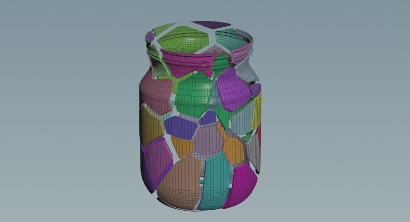
RBD Constraint Properties SOP lets you define how strong the pieces will glue together. Connect the first two inputs with the RBD Constraints from Rules node’s first two outputs. -
In the Glue subpane, look for Strength. This parameter sets the glue force between the fragments to make them stick together and create clusters. The image below shows the constraints structure of a jar object.
Note
The RBD Material Fracture SOP has its own Constraints tab, where you can create and adjust constraints directly without having to use properties and rules.

RBD Bullet Solver settings 
The solver processes the incoming geometry, constraints and collision data to simulate the objects' motion and behavior. In SOP-based setups there’s only the ![]() RBD Bullet Solver SOP. The solver also provides an in-built, infinite collision ground and methods for displaying the various forces, acting on the constraints. The solver also controls a simulation’s precision through substeps and iterations. Higher substeps often help to fix unwanted behavior, while iterations can be used to stabilize constraints.
RBD Bullet Solver SOP. The solver also provides an in-built, infinite collision ground and methods for displaying the various forces, acting on the constraints. The solver also controls a simulation’s precision through substeps and iterations. Higher substeps often help to fix unwanted behavior, while iterations can be used to stabilize constraints.
-
Add a RBD Bullet Solver SOP from the TAB menu.
-
Depending on which method you're using, you have to connect different nodes to the solver. Connect the three outputs of the solver’s direct upstream node (RBD Material Fracture or RBD Constraint Properties) with solver’s first three inputs.
-
Open the Collision tab’s Ground Collision subpane. Set Ground Type to Ground Plane. If necessary, change the ground plane’s Position. Alternatively, you can also add a
 Transformation SOP and change the position of the fractured object.
 -
Proceed with the default settings and press
 in the playbar to simulate. If you want to use custom objects as colliders, they go into the solver’s fourth input.
RBD Pack node 
Sometimes, fragmented objects consist of several thousands of individual pieces, large amounts of constraints and a wide range of attributes. The ![]() RBD Pack SOP is a very effective way to “compress” the simulation into three primitives - one for each node input. Packed RBD simulations are easier to handle, faster to render, easier to merge and more resource-friendly. The RBD Pack SOP is added after the RBD Bullet Solver.
RBD Pack SOP is a very effective way to “compress” the simulation into three primitives - one for each node input. Packed RBD simulations are easier to handle, faster to render, easier to merge and more resource-friendly. The RBD Pack SOP is added after the RBD Bullet Solver.
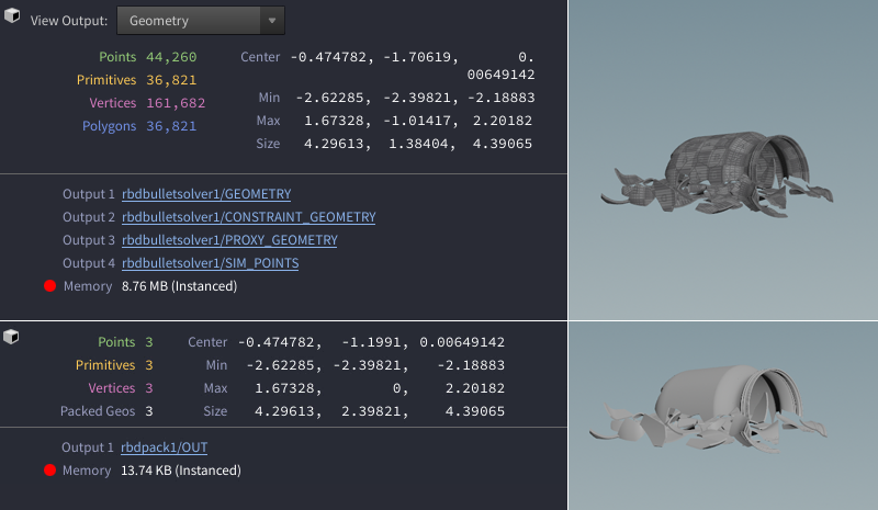
The ![]() RBD Unpack SOP reverts the packing operation and makes the original information, including attributes, available again. The unpacked simulation in the image below allocates up to 8.8 MB RAM. The packed version uses only 13.7 KB.
RBD Unpack SOP reverts the packing operation and makes the original information, including attributes, available again. The unpacked simulation in the image below allocates up to 8.8 MB RAM. The packed version uses only 13.7 KB.
In scenes with multiple packed RBD objects, consider using the Name parameter. A unique name serves as an identifier and keeps things clearly separated.
Simulation and Export 
Once the simulation is setup for the required effect, it can be simulated locally or through a Render Farm. For more information on how to export a simulation, visit Caching simulations.