| On this page |
On the Feather scattering and Applying feathers pages you've learned how to use two fundamental methods of adding feathers: scattering, drawing and planting. The good thing with drawing is that you only need several so-called guides instead of hundreds or thousands of individual feathers. The feathers between the guides are then interpolated through a special node. A process that has already been explained in outline here.
Guides are created through a ![]() Guide Groom SOP. The Draw tool literally lets you “pull” out feathers from the character’s surface. You can also mirror the guides for an even faster workflow.
Guide Groom SOP. The Draw tool literally lets you “pull” out feathers from the character’s surface. You can also mirror the guides for an even faster workflow.
This page picks up where Applying feathers left off and below is the network. Note that the feathers are stored in a separate container (/obj/atlas/ATLAS)

And to refresh your memory, below are the guides that will be used for the following considerations. As you can see, the guides have different length and orientation.

Hair Generate SOP 
If you're familiar with grooming hair and fur in Houdini, you’ll recognize many of the workflows described here. The methods are often very similar and use the same nodes. One of those nodes is the ![]() Hair Generate SOP. This node scatters hair on a surface or creates it from points. The hair will then be used to apply the feathers.
Hair Generate SOP. This node scatters hair on a surface or creates it from points. The hair will then be used to apply the feathers.
-
Add a Hair Generate SOP to the network, shown in the first image above, and turn on its blue Display/Render flag.
-
Connect the Hair Generate SOP’s
-
first input with the second output of the Guide Groom SOP ( Skin → Rest Skin)
-
second input with the first output of the Guide Groom SOP (Guides → Guides).
-
-
Open the Attributes & Appearance tab and scroll down to the Guide Attribute Transfer section. On the Point Attributes parameters, enter
barborient. This attribute is required to align the instances with the guides.
Before you can start to make your adjustments and see the result, you need another node. Please proceed with the chapter directly below.
Guide Interpolation Mesh 
This node generates a special type of low-resolution mesh that is required to interpolate the guides by adding a guides and weights attribute pair.
-
Add a Guide Interpolation Mesh SOP to the network.
-
Connect the Guide Interpolation SOP’s
-
first input with the first input of the Guide Groom SOP (Guides → Guides)
-
second input with the second input of the Guide Groom SOP (Skin → Skin).
-
output with the fifth input of the Hair Generate SOP (Output → Hair Interpolation Mesh).
-
You can often proceed with the guide mesh node’s default settings, but if you want to refine or change the guide mesh’s geometry, go to the Mesh section. There you can, for example, adjust the mesh’s quality with the Iterations parameter. Higher values will decrease the number of polygons. When you turn off Remesh, the node uses the character’s original resolution (left image).

Interpolation settings 
Now you have everything to make your final settings on the Hair Generate SOP to create a dense and fluffy “fur”.
-
On the General tab, go to the Guide Weights section.
-
Turn on Compute Weights Using Skin Coordinates. This function reads out the
weightsattribute from the interpolation mesh. This attributes cares for an even distribution of the feathers. Here’s a preview with the option turned off and on.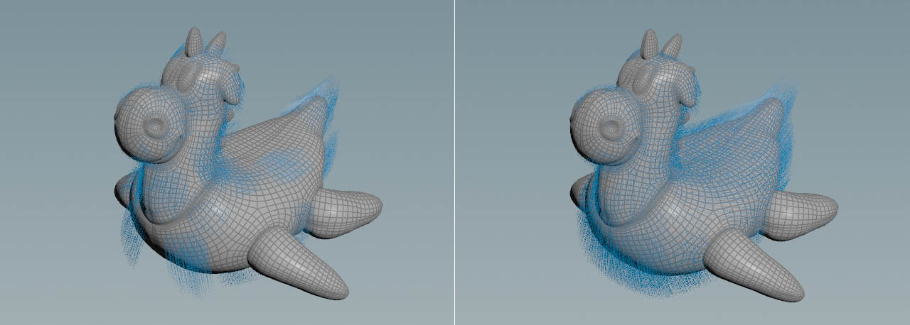
-
Turn on Use Interpolation Mesh to use the low-res version of the character.
-
From the Skin Guide Mode dropdown, choose Weight Array Pair (guides & weights). This option combines the attributes
guidesandweightsto interpolate the hairs. Now you can also see that hairs follow the guides. They also have different lengths and orientations. -
You might have seen that the node also adds hairs in areas without feather guides. To get rid of these feathers, go to Unguided Hairs and turn off Grow Unguided Hair.
-
To change the number of interpolated feathers, scroll to the Distribution section and change Density. Higher values create more hair/feathers.

Fetching the feather geometry 
As mentioned before, feathers and groom are located in separate ![]() Geometry OBJs. This separation is not mandatory and you can put everything into one geometry context as well. However, in templates with 20, 30, or more feathers things can quickly become confusing.
Geometry OBJs. This separation is not mandatory and you can put everything into one geometry context as well. However, in templates with 20, 30, or more feathers things can quickly become confusing.
-
Add an
 Object Merge SOP to the current network.
 -
Go to Object1 and click the
 Open floating operator chooser button. A floating panel with a scene tree appears. Navigate to the
  Null SOP that terminates the network with the feather geometry. In this example, the path is
 /obj/feathers/ATLAS.
You might remember that you already connected the ATLAS null inside the Guide Process SOP to select the body and down templates. In this step, however, you have to connect ATLAS to another node. Therefore it’s necessary to “reimport” the feathers.
Feather Template Interpolate 
The third and last nodes brings everything together to finally create the feathers on the character’s original geometry.
-
Connect the Feather Template Interpolate SOP’s
-
first input with the first output of the Hair Generate SOP (Feathers → Hair Curves)
-
second input with the second output of the Hair Generate SOP (Skin → Skin)
-
fourth input with the output of the Object Merge SOP (Feather Templates → Output).
-
With the default settings and values, the result could look as in the image below. The node interpolates the feather shapes using the templatenames, templateweights and barborient attributes.

Deintersecting feathers 
When you take a close look at the result, you will see that many feathers intersect each other. The feathers of real birds, however, are arranged like overlapping shingles. The ![]() Feather Deintersect SOP lets you separate the feather and avoid intersections. Feather deintersecting is GPU-accelerated, but with lots of feathers and less-performant GPUs, the process can be slow.
Feather Deintersect SOP lets you separate the feather and avoid intersections. Feather deintersecting is GPU-accelerated, but with lots of feathers and less-performant GPUs, the process can be slow.
Here you can see the entire network.

-
Add a
 Feather Visualize SOP and connect its three inputs with the three outputs of the Feather Template Interpolate SOP.
 -
The node lets you define how the feathers are represented in the viewport. From the Barb Mode dropdown menu, choose Surface to create a polygon version of the feathers.
-
You can also lay down a
 Color SOP. This node is not mandatory and not depicted in the network graph above. Colors can help you to identify intersections by applying random colors to the feathers. Connect the node’s input with the first output of the Feather Visualize SOP.
 -
From the Class dropdown, choose Primitive, because you want to dye the feather objects.
-
Set Color Type to Random
-
Lay down the Feather Deintersect SOP and link its first input with the output of the Color SOP. The second and third inputs are connected with the appropriate outputs of the Feather Visualize SOP.
Start with the Feather Deintersect node’s default settings to see if they're already sufficient. The most effective parameter to deintersect the feathers is Feather Geometry ▸ Thickness, where you can control the feathers' volume. Higher values create a stronger separation effect and you get a fluffier impression.
The node also resamples shaft and barbs to achieve better results. With Iterations you control the quality of the deintersection process. Higher settings create better results, but at the expense of performance.
The comparison below shows the feathers before and after the deintersection process.

