| On this page |
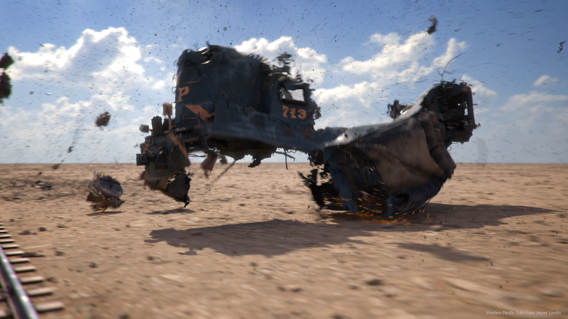
The ![]() MPM Post-Fracture fractures the renderable geometry represented in an MPM simulation using the final frame of the simulation. It attempts to fracture the geometry exactly where things are breaking or bending so that the renderable geometry can accurately capture the dynamics of the MPM simulation while preserving all of its original attributes.
MPM Post-Fracture fractures the renderable geometry represented in an MPM simulation using the final frame of the simulation. It attempts to fracture the geometry exactly where things are breaking or bending so that the renderable geometry can accurately capture the dynamics of the MPM simulation while preserving all of its original attributes.
The ![]() MPM Deform Pieces transfers the dynamics of the MPM simulation onto the renderable geometry. The renderable geometry must first be fractured using the
MPM Deform Pieces transfers the dynamics of the MPM simulation onto the renderable geometry. The renderable geometry must first be fractured using the ![]() MPM Post-Fracture once you are satisfied with the dynamics of the MPM simulation.
MPM Post-Fracture once you are satisfied with the dynamics of the MPM simulation.
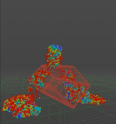
Before MPM Post Fracture and MPM Deform Pieces
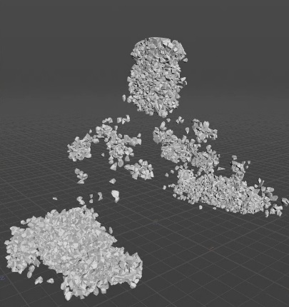
After applying MPM Post Fracture and MPM Deform Pieces
In comparison with the RBD workflow, this might feel a little bit backward. With MPM, first you get the simulation that you like, then you use the last frame of the simulation to fracture the renderable geometry, and lastly you retarget the dynamics of the MPM simulation onto the fractured geometry. This has the benefit of allowing the geometry to dynamically fracture where it needs to instead of blindly predefining where things can break. On the other hand, you need to refracture the renderable geometry each time the MPM simulation changes.
Note
You must always set an End Frame on the ![]() MPM Post-Fracture node because this node is looks at this last frame and evaluates the state of the material, and based on this state ,it’s going to fracture the geometry.
MPM Post-Fracture node because this node is looks at this last frame and evaluates the state of the material, and based on this state ,it’s going to fracture the geometry.
Warning
The deformation gradient F needs to be cached for the destruction workflow. It is not by default. You must turn on the Deformation Gradient (F) checkbox on the Output tab of the MPM Solver.
MPM Post Fracture 
Once you set the End Frame on the MPM Post Fracture node, you can turn off the Perform Fracture checkbox temporarily. You will still see guides to give you an general idea of what you're generating, but you don’t have to pay the cost of fracturing the geometry every single time you change a parameter.
The Global Scale parameter is another time saving feature, since all of the parameters are scale dependent. For example, if you set up this node for a building to fracture perfectly, you can then apply it to another asset that you want to look exactly the same, even if it’s a different size. You can get the same look for the fractures and same details for the cracks by using this multiplier to adjust everything to scale.
There are three steps (tabs) to configure your fracture. The first step is to define which pieces are going to be fractured, on the Pieces Selection tab. You can set the minimum length for a piece to be considered for fracturing. Anything smaller than this amount will be excluded. If you turn on Show Guides, piece large enough to be considered for fracturing will be outlined in green, and pieces that are too small to fracture will be outlined in red.
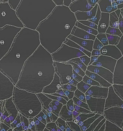
The second step is to define what MPM points are going to be used to fracture the geometry on the Fracture Points tab. Turning on Align Fractures to Stretch Points is a very useful tool when fracturing metal, as well as other types of materials, as it helps align the cracks in the right place. It uses the immediate neighbors to the points selected by stretch thresholding as piece centroid to be used for the fracturing.
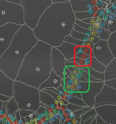
Fracture crack before turning on Align Fractures to Stretch Points
You can see that the area in green fractures as expected, with one point per piece. The area in red shows isolated points with no neighbors next to them. This creates floating pieces, as you don’t know which direction the piece will fold, so the generated crack might look unnatural.
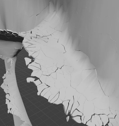
Fracture line after turning on Align Fractures to Stretch Points
You can see improved alignment between the geometry fractures and the MPM fractures.
You can also specify the minimum stretching amount for the point to be considered breaking, as well as prevent two overlapping points from being selected. If you have points that are too close to each other, it’s going to slow down the fracturing process and can lead to a broken geometry.
All of the white points that are visualized in the example above are not MPM points, but are that are added near the fracturing region to allow the geometry to flex a little bit to avoid having very elongated pieces that will not be transformed properly. Increasing the Filler Points will result in more resolution and nicer bending of the geometry near the fracturing regions.
Lastly, if you have the Cutter Method set to Boolean, you can add some resolution in the Cutter Geometry tab. Options on this tab allow you to add more noise, creating a more natural looking fracture.
MPM Deform Pieces 
This node lets you choose how the MPM dynamics will be applied to the fractured geometry with the Retargeting Type. It can be used as part of the destruction workflow, or without the MPM Post Fracture node. Piece (Transform) is useful for fracturing something like a smashed watermelon, as it transform each piece of the fractured geometry with a single transformation extracted from the MPM points. Piece (Deform) deforms each point of the fractured geometry with its nearest MPM point at rest, and is often use for debugging. Piece + Point is combination of these two methods, and is driven by the Stretch Ratio Tolerance. It defines the amount of piece deformation that will trigger a smooth transition from the deformation to the transformation. Very high values will be equivalent to using the Point (Deform) type while a value of 0 will be equivalent to using the Piece (Transform) type.
Depending on the type of material you're fracturing, you may need to use this node to make some further adjustments. For example, when fracturing concrete, it’s natural to see small cracks where the material hasn’t fully broken. However, this looks unnatural when fracturing a material like metal. In this case, you can turn on the Close Gaps checkbox to close cracks that appear when a piece is transitioning from deforming to transforming. This is especially useful when simulating plastically deformable material like metal where things can stretch a fair bit before actually tearing.
Close Gaps turned off
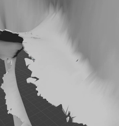
Close Gaps turned on