| On this page |
There are several MPM Configure examples available through the tab menu. These are similar to shelf tools that put down networks of nodes for learning purposes. The MPM Configure Building Collapse example illustrates the use of the Concrete material type. It puts down a simple network of nodes to simulate a building being hit by a meteorite and collapsing.
Important nodes 
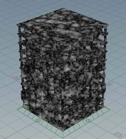
building_model and meteorite
These are both ![]() MPM Sources using the Concrete material preset. The Density and Stiffness on the
MPM Sources using the Concrete material preset. The Density and Stiffness on the meteorite node is multiplied by 10× and 2x, respectively, so that it’s able to break through the building. It also has a strong initial Velocity applied.
noise_E_attribute
This is an ![]() Attribute Wrangle node that adds some spatial variation to the stiffness of the building, causing it to collapse in a more interesting way.
Attribute Wrangle node that adds some spatial variation to the stiffness of the building, causing it to collapse in a more interesting way.
merge_sources
A ![]() Merge node merges the two MPM sources before feeding them into the solver.
Merge node merges the two MPM sources before feeding them into the solver.
mpmcontainer
The ![]() MPM Container defines the resolution of the simulation using the Particle Separation parameter. This parameter is increased slightly to increase the resolution of the whole simulation.
MPM Container defines the resolution of the simulation using the Particle Separation parameter. This parameter is increased slightly to increase the resolution of the whole simulation.
mpmsolver
On the Visualize tab of the ![]() MPM Solver, the Color From Attribute checkbox is turned on, and the
MPM Solver, the Color From Attribute checkbox is turned on, and the Jp attribute is being visualized. This is the determinant of the plastic component of the deformation gradient. It basically highlights where things are either stretching (breaking) or compressing in a permanent way. The solver is not going to try to recover from the plastic deformation, as opposed to the elastic deformation. This Jp attribute can be used to trigger secondary emission like debris and dust. In this example, you will be able to see the cracks that are being highlighted as the meteorite hits the building.
fractured_meteor
This ![]() MPM Post-Fracture fractures the meteor geometry according to its final MPM state at the end of the MPM simulation, which is defined by the End Frame parameter. In the Fracture Points tab, Align Fractures to Stretch Points is turned off to allow each stretching point to be used as a fracture centroid. The fillers' Point Separation has been increased to reduce their amount and the Maximum Distance has been reduced to only add filler points near MPM fracture points. In the Cutter Geometry tab, the Add Interior Details checkbox has been turned on to get more interesting fractures.
MPM Post-Fracture fractures the meteor geometry according to its final MPM state at the end of the MPM simulation, which is defined by the End Frame parameter. In the Fracture Points tab, Align Fractures to Stretch Points is turned off to allow each stretching point to be used as a fracture centroid. The fillers' Point Separation has been increased to reduce their amount and the Maximum Distance has been reduced to only add filler points near MPM fracture points. In the Cutter Geometry tab, the Add Interior Details checkbox has been turned on to get more interesting fractures.
fractured_building
This ![]() MPM Post-Fracture fractures the building according to it’s final MPM state at the end of the MPM simulation, which is defined by the End Frame parameter. In the Fracture Points tab, Align Fractures to Stretch Points is turned off to allow each stretching point to be used as a fracture centroid. The fillers' Point Separation has been increased to reduce their amount and the Maximum Distance has been reduced to only add filler points near MPM fracture points. In the Cutter Geometry tab, the Add Interior Details checkbox has been turned on to get more interesting fractures.
MPM Post-Fracture fractures the building according to it’s final MPM state at the end of the MPM simulation, which is defined by the End Frame parameter. In the Fracture Points tab, Align Fractures to Stretch Points is turned off to allow each stretching point to be used as a fracture centroid. The fillers' Point Separation has been increased to reduce their amount and the Maximum Distance has been reduced to only add filler points near MPM fracture points. In the Cutter Geometry tab, the Add Interior Details checkbox has been turned on to get more interesting fractures.
deformed_building
This ![]() MPM Deform Pieces takes the fractured pieces defined by the two upstream
MPM Deform Pieces takes the fractured pieces defined by the two upstream ![]() MPM Post-Fractures feeding into its first input and deforms them using the MPM particles in the second input, applying the Point + Piece Retargeting Type.
MPM Post-Fractures feeding into its first input and deforms them using the MPM particles in the second input, applying the Point + Piece Retargeting Type.
Learning from this example 
| To... | Do this |
|---|---|
|
Visualize the areas of varied stiffness in the concrete |
Tip You can turn on the Bypass flag on for this node to see how the addition of varied stiffness affects the way the concrete breaks apart. |