| On this page |

Overview 
 MPM Surface SOP creates a surface based on an MPM simulation. It can output VDBs as well as polygon meshes. This node comes with many functionalities to streamline the process of turning your MPM simulation into renderable geometry.
The node behaves similarly to the  Particle Fluid Surface SOP used for FLIP simulations, but it is designed specifically for MPM particle data. When connected directly to the output of an MPM simulation, the node automatically determines an appropriate voxel size and resolution based on the simulation container settings, allowing you to quickly generate a signed distance field representation of the particles.
For your Output Type, you can choose between Surface VDB, Density VDB, and Polygon Mesh. Each output type has its own set of controls available in the node’s parameter interface.
Surface generation methods 
You can choose between the VDB from Particles or Neural Point Surface methods for generating the surface grid.
Neural Point Surface 
The Neural Point Surface method uses the  Neural Point Surface node to generate the
 surface grid using a pre-trained neural network. This is the newer and more experimental approach, but it often produces high-quality surfaces with minimal parameter adjustments.
There are several pre-trained models are included and optimized for different types of materials.
-
Balanced – general purpose model
-
Smooth – removes small details for smoother surfaces
-
Liquid – optimized for fluid-like materials
-
Granular – optimized for granular materials such as sand, soil, or snow
-
Custom - allows you to train your own model
This approach works particularly well when running on a high-end GPU with sufficient memory. Internally the neural inference uses ONNX models, and performance may decrease significantly when running on CPU-only systems.
One advantage of the neural approach is that it performs localized surface reconstruction, meaning calm regions of the surface are smoothed while areas with more motion or detail retain sharper features.
VDB from particles 
The VDB from Particles method uses a combination of VDB rasterization and morphological operations to generate the surface grid. This is the more robust and traditional approach, however you will most likely need to tweak the parameters to get the desired look.
The Filtering options include Dialate, Smooth, and Erode, which are applied sequentially and can be used to reduce noise or refine the generated surface.
This method is generally preferred if you have a lower-end or mid-range GPU, or when working with very large simulations involving millions of particles.
Mask smoothing 
The Masked Smooth options allow smoothing to be applied selectively. This feature uses simulation attributes such as Jp (stretch) and surface curvature to determine which regions should be protected from smoothing. Regions where particles are stretching or where curvature exceeds a threshold are excluded from the smoothing operation.
This allows flat regions of the surface to be smoothed, and highly detailed regions, such as breaking material or edges, to remain sharp. Turning on Visualize for Min Stretch and Min Curvature will let you see which areas are protected from smoothing.
Velocity field generation 
The controls on the Velocity tab allow you to generate a velocity VDB alongside the surface grid. This velocity field can be used for secondary effects such as debris emission or particle advection. By default, the velocity field is generated using a larger voxel size than the surface grid in order to reduce disk usage and memory consumption.
Attribute transfer 
When generating a Polygon Mesh, attributes from the MPM particles can be transferred to the resulting geometry by turning on From MPM Particles in the Attribute Transfer section of the Polygon Mesh tab. For example, particle color (Cd) or other simulation attributes can be projected onto the mesh. By default all attributes are transferred, but you can select individual attributes from the Attribute List.
Partitioning 
Another useful feature is the ability to partition the point cloud so that large point clouds can be processed on OpenCL devices with limited memory. However, this option should only be turned on if your OpenCL device (GPU) is running out of memory while cooking the node, as it may degrade performance and should be used only when necessary. This option is only available when using the Neural Point Surface method.
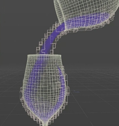
Enable Partitioning off
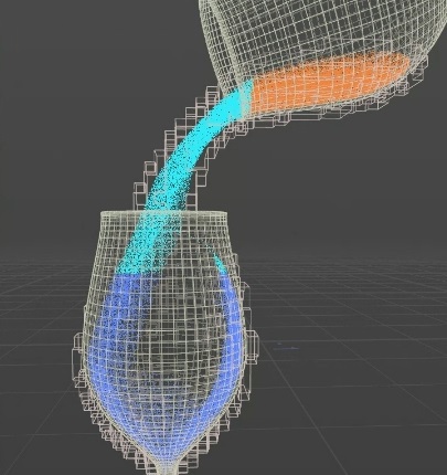
Enable Partitioning on, with three partitions created
Node inputs 
There are some unique inputs on this node to be aware of. The second input takes the output of the MPM Surface, which is useful to split the SDF creation from the polygon mesh creation in two separate steps. For example, if you need a collider representation of the MPM particles for secondary simulation, this prevents you from having to recompute everything from scratch since you will already have a representation of the surface as a volume and the velocity field. To save on computation, you can just take the output of one MPM Surface node and plug it into the second input of another MPM Surface node. It allows you to cache the SDF representation as a collider for another simulation, and then cache the version you need for rendering.
The third input takes the renderable geometry used by the  MPM Source. This is useful when you want to transfer UVs. You can provide the source model at its rest position, and when connected to the third input, you can transfer UVs per island.
The fourth input uses a VDB surface used as a mask to prune polygons that would not be visible at render time. In the landslide example, you could use the slope as a mask to reduce the amount of polygons generated by the MPM Surface.
See Neural point surfacing for more information.