| On this page |
Overview 
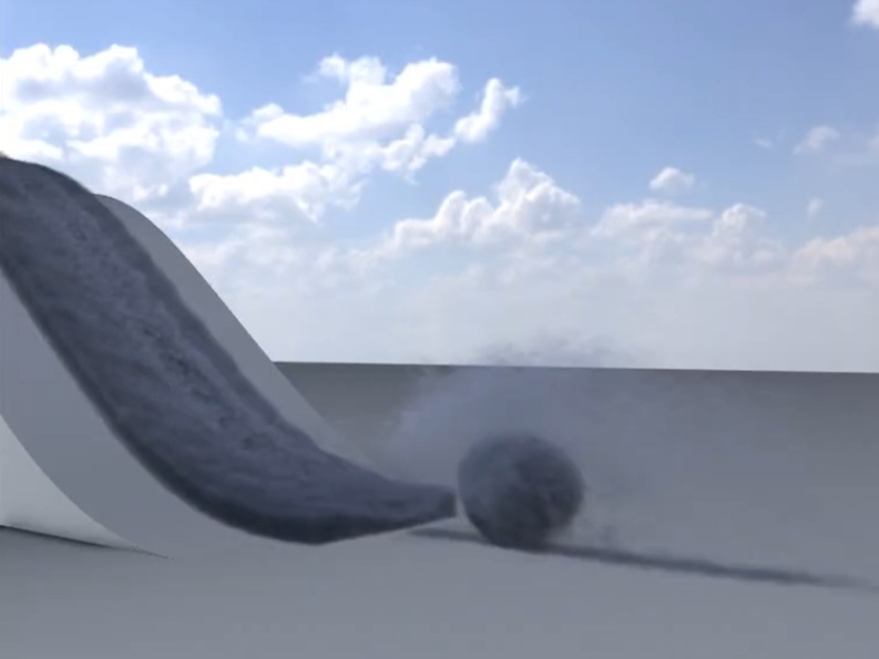
 MPM Debris Source extracts points of potential emission for secondary simulations derived from a primary MPM simulation. It detects areas where the material is stretching or moving quickly and creates emission points that can drive secondary simulations such as debris.
The output of this node is typically connected to a  POP Solver, where the generated points act as emission sources. The MPM surface SDF is often used as a collider for the secondary simulation. This node adds higher-frequency detail to an MPM simulation without increasing the resolution of the primary simulation.
Inputs 
The first input of the MPM Debris Source is the particle output from an MPM simulation. These particles contain attributes used to determine where debris should be emitted.
The second input is optional and provides the volumetric representation of the MPM simulation. This typically contains a surface SDF and a velocity field, and is used to determine proximity to the simulation surface and to restrict emission to surface regions.
How it works 
The node reads timing information such as Start Frame and Time Scale from detail attributes stored on the MPM simulation. You can override these values if necessary. By default, emission occurs on integer frames.
The Prune Points section determines which particles from the MPM simulation will be used as emission sources.
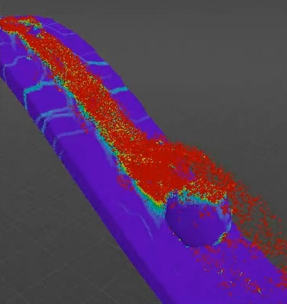
Minimum Stretching uses the jp attribute to detect where the material is stretching or breaking. Higher values restrict emission to regions with stronger deformation. The image below shows the visualization of the jp attribute on a simulation of a snowball rolling down a slope.
Minimum Speed sets the minimum particle speed required for emission. Increasing this value prevents emission from slow or static particles.
Max Dist to Surface ensures that emissions occur close to the surface, producing more natural-looking secondary simulations. It restricts emission to particles within a distance band around the surface of the simulation. Limiting emission to the surface helps avoid particles emitting debris from deep inside the material, which can produce unnatural behavior in secondary simulations. The distance is measured relative to the simulation voxel size (dx), so the parameter automatically scales with the resolution of the simulation.
Ratio to Keep lets you dial back the amount of emission by randomly reducing the number of emission points. Lower values keep fewer points and can be used to control emission density.
The Replicate Points section lets you generate additional emission points based on stretching or speed. For example, if something is breaking a lot or going very fast, you may want to generate more points.
You can turn on Spread Points Along Velocity if you want to distribute emission points along the particle velocity direction between frames. When this option is off, emission occurs only on integer frames, which may produce stepping artifacts in emission trails. Spreading points along velocity produces smoother, continuous emission.
Most attributes are removed from the output points. The node keeps only the attributes required for secondary simulations such as pscale, v, and orient.
Tips 
-
Use Minimum Stretching to target areas where the material is breaking.
-
Use Minimum Speed to avoid emitting debris from static regions.
-
Turn on Max Dist to Surface to keep emissions near the material surface.
-
Reduce Ratio to Keep if the node generates too many emission points.
-
Turn on Spread Points Along Velocity to avoid stepping artifacts in debris trails.