| On this page |
|
Overview 
Flags are bits of state information on the node. Different network types have different flags on the nodes.
The flags available on a given node are specific to the network type:
Setting flags 
-
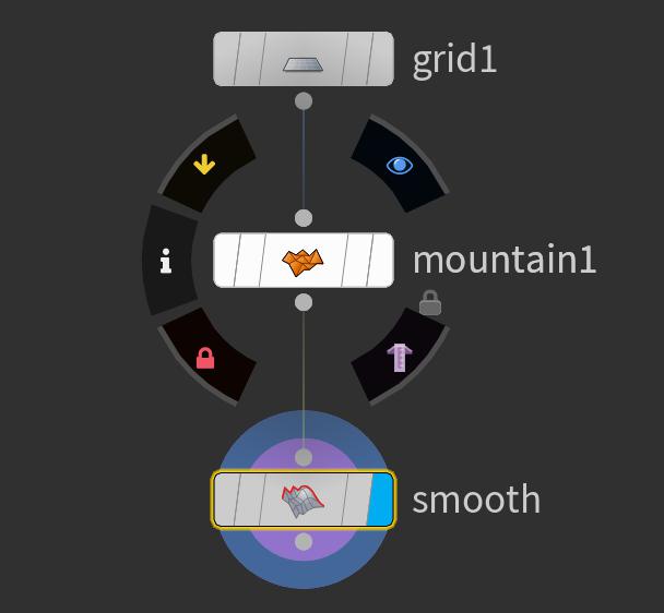
Usually flags are toggles: clicking them toggles them on and off. When a flag is on it is filled with color. When it’s off it shows the node’s background color (gray by default).
-
Some flags are little more complex. For example, the display flag in surface node networks can only be on one node at a time. The node with the flag represents the geometry of the parent object. ⌃ Ctrl-clicking the flag sets the render flag, allowing you to use one geometry for display and a different geometry for rendering. See the
 surface node help for more information.
 -
Render nodes have a flag that is actually a button. It causes the node to render. See the
 render node help for more information.
 -
To turn a node flag on or off:
-
Click the flag area on the node body, do one of the following:
-
Hover the mouse pointer over the node to show the node ring. Buttons on the ring let you turn the flags on or off.
-
Use the hotkey for the flag.
-
-
Some nodes have seldom used flags that don’t fit on the node body. You can turn these flags on or off using the
 context menu on the node. The state of the flag is usually indicated by a badge instead of coloring a flag area on the node.
 -
You can select multiple nodes and click on of their flags to turn the flag on/off on all the selected nodes. For example, to bypass multiple surface nodes at once, select them and click the yellow bypass flag on one of them.
Flag hotkeys 
Some flags have hotkey equivalents. Q, W, E, R and T are used as flag hotkeys in the network editor. The different keys control different flags depending on the network.
-
Q or B is always bypass.
-
The key letters are not usually mnemonic, though some are. We prioritized keeping the keys together in a row so you could rest your fingers on them. R is usually the most commonly changed flag, then E, then T, then W.
You can use flag hotkeys in two ways:
-
Select the node(s) you want to change and tap the key.
or
-
Hold the key and click a node to set/clear the flag on that node.
This is easier for tablet users. It can also be useful when you want to, say, hold the display flag key and click around the network to move the display flag quickly.
Set Primary Flag
Hold this key and select a node to toggle the primary flag value
Set Secondary Flag
Hold this key and select a node to toggle the secondary flag value
Set Third Flag
Hold this key and select a node to toggle a third flag value
Set Fourth Flag
Hold this key and select a node to toggle a fourth flag value
Set Bypass Flag
Hold this key and select a node to toggle the bypass flag value
Badges 
See badges.
Object network 
The Object or “Scene” level (/obj/) contains the “top-level” ![]() objects of your scene (geometry objects, skeletons, lights, cameras) and lets you set up the spatial and hierarchical relationships between them.
objects of your scene (geometry objects, skeletons, lights, cameras) and lets you set up the spatial and hierarchical relationships between them.
The object level is where you position the characters, props, cameras, and lights in a scene. You model the actual surfaces that define skin/shape of the characters and props inside ![]() Geometry object nodes using geometry nodes (SOPs).
Geometry object nodes using geometry nodes (SOPs).
Wiring nodes together at the Object level create hierarchical (“parenting”) relationships.

Object flags 
Icon |
Key |
Description |
|---|---|---|
|
E |
Selectable. When this node is off, it is not selectable in the viewer. You can use this to make it impossible to accidentally select the object while you are working on other objects. When the selectable flag is on, the flag on the left of the node is lit green. |
|
R |
Display. If this is off, the object does not appear in the viewer. When the display flag is on, the flag on the right of the node is lit blue. |
Other Object flags 
You can set these flags by ![]() clicking a node and opening the Flags sub-menu.
clicking a node and opening the Flags sub-menu.
Display Origin
Show a jack at the object’s origin point. Turning off the display flag hides the jack as well.
X-ray
Make the object visible behind other geometry. This is used to make bones visible inside the character’s skin.
Geometry (SOP) networks 
A ![]() Geometry object at the object level contains a geometry (SOP) network inside. This network holds the
Geometry object at the object level contains a geometry (SOP) network inside. This network holds the ![]() geometry nodes that create the object’s geometry.
geometry nodes that create the object’s geometry.
Wiring nodes together at the geometry level controls the flow of geometry through the nodes, from nodes that generate new geometry (such as ![]() Sphere) through nodes that modify the geometry.
Sphere) through nodes that modify the geometry.

See geometry for more information on using geometry nodes.
SOP flags 
Icon |
Key |
Description |
|---|---|---|
|
Q or B |
Bypass disables the node, making it pass its input geometry through to the output unchanged. This is useful for testing and visualizing the effect the node is having in the viewer. When a node is bypassed, the flag on the left of the node is lit yellow. |
|
None |
Lock “freezes” and caches the node’s output geometry. While the node is locked, the node outputs the “frozen” geometry instead of cooking. This is usually not necessary and can be confusing, (which is why the flag isn’t clickable on the node and doesn’t have a hotkey), but it has two potential benefits:
When a node is locked, the flag second from the left of the node is lit red, and a badge appears on the node. Don’t confuse this “lock” with locked digital assets. |
|
E |
Template makes the node’s geometry visible (and snap-able) in the viewer even if the node doesn’t have the display flag on. You can control how templated geometry is drawn in the viewport (for example, as wireframe, or shaded) in the viewport display options. Normally, clicking the template flag on a node turns off the template flag on all other nodes. You can ⇧ Shift-click template flags to template multiple nodes at once. When the template flag is on, the flag second from the right of the node is lit maroon, and a maroon ring appears around the node. |
|
R |
Display marks the node whose geometry appears in the 3D viewer. Often this is at the end of the network, showing the cumulative output of the network, but you can (and will often) move the display flag around the network to check the output of different nodes. Normally, moving the display flag also moves the Render flag, but you can separate them, so you can set one node to provide the geometry in the viewer, and another node to provide geometry at render time. This can be useful to show proxy geometry in the viewer and render more detailed geometry. When the display flag is on, the flag on the right of the node is lit blue, and a blue ring appears around the node. |
|
T |
Render When the render flag is on, the flag on the right of the node is lit purple, and a purple circle appears around the node. |
Other SOP flags 
You can set these flags by ![]() clicking a node and opening the Flags sub-menu.
clicking a node and opening the Flags sub-menu.
Icon |
Key |
Description |
|---|---|---|
|
W |
You can ⌃ Ctrl-click the template flag to set the Selectable Template flag. This makes the geometry visible and allows you to select components from the templated geometry in the viewport, in addition to components on the geometry with the display flag. If you apply an operation (for example, |
|
None |
The Unload flag tells Houdini not to cache the geometry output by the node. This saves memory, but slows down cooking. An exception is geometry that is being displayed, which will remain cached, since it is still in use. When the node has the unload flag, a badge appears on the node. |
Dynamics node (DOP) networks 
DOP networks contain dynamics nodes (DOPs) that create or load objects and forces, establish the connections between them, and configure solvers for simulating their interactions.
If you use dynamics shelf tools, they will create a DOP network for you if necessary. You can also create your own DOP network at any network level of the scene.
You can have multiple DOP networks containing separate simulations. The dynamics menu lets you choose which network the shelf tools use.

See dynamics for more information on using dynamics nodes.
DOP flags 
Icon |
Key |
Description |
|---|---|---|
|
Q or B |
Bypass disables the node, making it pass its data tree through to the output unchanged. This is useful for testing and visualizing the effect the node is having in the viewer. When a node is bypassed, the flag on the left of the node is lit yellow. |
|
E |
Hidden When the hidden flag is on, the flag second from the right of the node is lit cyan. |
|
R |
Output marks the node whose output is used as the data tree for the simulation. Often this is at the end of the network, showing the cumulative output of the network, but you can move the display flag around the network. When the display flag is on, the flag on the right of the node is lit orange, and an orange ring appears around the node. |
Copernicus node (COP) networks 
A COP network contains Copernicus nodes for real-time image manipulation in a 3D space. You can manually add a COP network or use the default COP network Houdini creates at /img (see How to access Copernicus).
Wiring COPs together controls the flow of layer and geometry data, from nodes that load or generate this data through nodes that modify the data.
Copernicus nodes have a different node body from other network nodes:
-
Copernicus nodes include a preview thumbnail in the node body. To hide or show the preview thumbnail, click the arrow in the bottom left corner of the node.
-
For nodes with multiple outputs, click the output name in the bottom right of the node to select which output displays.
-
You can’t assign custom shapes to COPs because they have a unique layout.
See Working with Copernicus nodes for more information about using Copernicus nodes.

COP flags 
Icon |
Key |
Description |
|---|---|---|
|
Q or B |
Bypass disables the node, making it pass its input image through to the output unchanged. This is useful for testing and visualizing the effect the node has in the viewer. When a node is bypassed, the flag on the left of the node is lit yellow. |
|
W |
Shaded Template makes the node’s image visible (and snap-able) in the 3D viewer even if the node doesn’t have the display flag on. This lets you select components from the templated image in the viewport and components on the image with the display flag. To reset all shaded template flags, turn the flag on and then off on a random node. When the shaded template flag is on, the flag second from the right of the node is lit purple and a purple ring appears around the node. |
|
E |
Template makes the node’s image visible (and snap-able) in the 2D and 3D viewer even if the node doesn’t have the display flag on. When in the 3D viewer, the output of any nodes with the template flag on is shown as a gray outline. Use the shaded template flag instead of the template flag when you're in the 3D viewer to see more than an outline of the image. When the template flag is on, the flag second from the right of the node is lit pink and a pink ring appears around the node. |
|
R |
Display marks the node whose output appears in the COP viewer. Often this is at the end of the network, showing the cumulative output of the network, but you can (and will often) move the display flag around the network to check the output of different nodes. When the display flag is on, the flag on the right of the node is lit blue and a blue ring appears around the node. 3D Output lets the 3D viewer display something different from the 2D viewer. ⌃ Ctrl + When the 3D output flag is on, the flag on the right of the node is lit orange. |
Compositing node (COP2) networks 
Old network
As of Houdini 20.5, use Copernicus nodes instead of Compositing nodes. Though both networks still exist, the Compositing network is now designated as COP Network - Old. The Compositing network and its nodes will be deprecated and then removed in a future Houdini release.
A Compositing network contains ![]() compositing nodes (COP2s) for manipulating 2D pixel data. This is useful for compositing images such as render passes, but you can also use COP2s to manipulate other pixel-based data, such as depth maps.
compositing nodes (COP2s) for manipulating 2D pixel data. This is useful for compositing images such as render passes, but you can also use COP2s to manipulate other pixel-based data, such as depth maps.
Houdini creates a default compositing network at /img. You can also create your own Compositing network at any level of the scene (for example, next to a render node that uses the Compositing network to process its output).
Wiring COP2s together controls the flow of image data, from nodes that load or generate image data through nodes that modify the i.
Compositing nodes have a different node body from other network nodes.

-
Compositing nodes include a preview thumbnail in the node body. To hide or show the preview thumbnail, click the arrow in the bottom left corner of the node.
-
To control which image plane the node displays, click the plane menu in the bottom right corner of the node.
-
Because of the special features built into compositing node, you cannot assign custom shapes to them.
You can view the image generated by a compositing network in the Composite View tab.
See compositing for more information on using compositing nodes.
COP2 flags 
Icon |
Key |
Description |
|---|---|---|
|
Q or B |
Bypass disables the node, making it pass its input image through to the output unchanged. This is useful for testing and visualizing the effect the node is having in the viewer. When a node is bypassed, the flag on the left of the node is lit yellow. |
|
T |
Template makes the node’s image diff-able in the viewer. You can use controls in the viewer UI to compare between the display output and the template output. When the template flag is on, the flag second from the left of the node is lit purple, and a maroon ring appears around the node. |
|
E |
Output marks the node whose output is used as the output for the entire network. When the output flag is on, the flag second from the right of the node is lit dark orange, and an orange circle appears behind the node. |
|
R |
Display marks the node whose output appears in the COP2 viewer. Often this is at the end of the network, showing the cumulative output of the network, but you can (and will often) move the display flag around the network to check the output of different nodes. When the display flag is on, the flag on the right of the node is lit blue. |
Render node (ROP) network 
Render networks contain render nodes (ROPs), which represent rendering jobs. Different nodes launch different renderers (for example, mantra or RenderMan). The node parameters specify options such as the frame range to render and the output filename.
Houdini creates a default render network at /out. Items in the top-level Render menu let you create and edit render nodes in this network. You can also create your own ROP networks at any level of the scene. For example, you might embed a render node in an asset as part of an ability to generate its own textures.
The ROP level does not require you to connect nodes: each node represents a renderer and configuration you can use to render the scene. However, you can connect ROP nodes together to create dependency graphs, allowing you to define dependency relationships between render passes.

See rendering for more information on using render nodes.
Render flags 
|
Q or B |
Bypass disables the node when it is part of a render dependency network, making it skip rendering. When a node is bypassed, the flag on the left of the node is lit yellow. |
|
None |
Lock prevents upstream dependencies from rendering. When a node is locked, the flag second from the left of the node is let red, and a badge appears on the node. Don’t confuse this “lock” with locked digital assets. |
|
T |
Render button. This opens a render dialog to let you start rendering from this node. This is not really a flag. |
VOP networks 
A VOP network contains ![]() VOP nodes that represent operations in the VEX shading language. You can build materials (shaders) using VOP networks. There are also many places in Houdini where you can use VOPs as a general purpose visual programming language to manipulate other types of data, such as geometry.
VOP nodes that represent operations in the VEX shading language. You can build materials (shaders) using VOP networks. There are also many places in Houdini where you can use VOPs as a general purpose visual programming language to manipulate other types of data, such as geometry.
Houdini creates a default shader VOP network at /mat. Various other node types contain VOP networks for modifying specific data, for example the ![]() Attribute VOP geometry node. You can create a standalone VOP network at any network level.
Attribute VOP geometry node. You can create a standalone VOP network at any network level.
VOPs have a different shape and network orientation than other network types. VOPs have multiple named inputs and outputs as part of the node body.

-
Click the icons in the bottom right corner of the node to switch it to more compact modes.
-
 shows all inputs.
 -
 shows only connected inputs. Other inputs go in a “More” menu at the bottom.
 -
 hides all inputs in a “More” menu.
You can click the “More” menu to choose an input to start wiring, or wire into the More menu to choose an input to connect to.
-
-
The white items in the input list with triangles next their names instead of circles are group headings. Click a group heading to collapse the group, or click a collapsed heading to expand it. When a group is collapsed, the heading acts like a “More” menu (see above).
-
You can hide inputs using the
 gear menu for individual parameters. This moves the hidden input to a “More” menu at the bottom of the inputs.
 -
Because of their unique layout, you cannot assign custom shapes to VOPs.
See shading for more information on using VOP nodes.
VOP flags 
Icon |
Key |
Description |
|---|---|---|
|
R |
Debug switches the node’s outputs to “debug” mode. You can set up each individual output to execute as normal, pass through an input, or output a constant when the node is in debug mode. To choose what an output does in debug, Alt + When the debug flag is on, the leftmost flag on the node is lit cyan. |
|
Q or B |
Bypass switches the nodes outputs to “bypass” mode. You can set up each individual output to either pass through an input or output a constant when the node is “bypassed”. To choose what an output does in bypass mode, Alt + |
|
None |
Material marks VOPs which represent materials for shading objects. VOPs with this flag on will appear in various user interfaces for choosing materials. When the material flag is on, the rightmost flag on the node is lit dark orange. |
Channel node (CHOP) networks 
A CHOP network contains ![]() channel nodes (CHOPs) for manipulating time-based channel data such as animation curves or audio.
channel nodes (CHOPs) for manipulating time-based channel data such as animation curves or audio.
Houdini creates a default CHOP network at /ch. You can also create your own CHOP networks at any level of the scene (for example, inside a character to control kinematics).
Wiring CHOPs together controls the flow of channel data, from nodes that load or fetch the channel data through nodes that modify the channels.
You can view the data generated by a CHOP network in the Motion FX View tab.

CHOP flags 
Icon |
Key |
Description |
|---|---|---|
|
Q or B |
Bypass disables the node, making it pass its channels through to the output unchanged. This is useful for testing and visualizing the effect the node is having in the CHOP viewer. When a node is bypassed, the flag on the left of the node is lit yellow. |
|
E |
Export overrides the channel corresponding to the node’s channel name with the data from the node. For example, you can name the channel generated by a node Normally, clicking the export flag on a node turns off the export flag on all other nodes. You can ⇧ Shift-click export flags to export multiple nodes at once. When the export flag is on, the flag second from the left of the node is lit bright orange. |
|
T |
Output sets this node’s output as the output of the CHOP network. When the output flag is on, the flag second from the left of the node is lit dark orange. |
|
R |
Display marks the nodes whose channels appear in the CHOP viewer. You can set/clear this flag on multiple nodes to see their channels in the viewer at the same time. Normally, clicking the display flag on a node toggles the flag only for that node. You can ⌃ Ctrl-click display flags to set an exclusive display flag and turn off the flags on all other nodes. When the display flag is on, the flag on the right of the node is lit blue. |
Other CHOP flags 
You can set this flag by ![]() clicking a node and opening the Flags sub-menu.
clicking a node and opening the Flags sub-menu.
Icon |
Key |
Description |
|---|---|---|
|
None |
Lock “freezes” and caches the node’s output channels. While the node is locked, the node uses the “frozen” channels instead of cooking. This is usually not necessary and can be confusing, (which is why the flag isn’t clickable on the node and doesn’t have a hotkey), but it has two potential benefits:
When a node is locked, a badge appears on the node. Don’t confuse this “lock” with locked digital assets. |
Task node (TOP) networks 
TOP networks contain task nodes that represent a series of tasks or work items to be performed. There are four main types of TOP node: processors that generate work items, schedulers that run the work item’s jobs, partitioners that join together incoming work items, and mappers that establish dependencies between otherwise unrelated work items.
With a TOP node network, you can create a scalable recipe for generating work items, running them locally or on a farm, establishing the network of dependencies between all the work items, and figuring out how to do it all as efficiently as possible. This recipe is called a PDG (Procedural Dependency Graph). For more information about TOPs and PDG, see Intro to TOPs.
Houdini creates a default task network (/topnet1) at /tasks, and a default scheduler (localscheduler) at /tasks/topnet1. Much like ROPs, you can create a standalone TOP network at any level of the scene. For example, you can create a TOP network in the /stage context to generate variations of LOP prims for a Solaris project.
The TOP level requires that you connect your nodes, all except for schedulers.
TOP flags 
For more information about how TOP nodes and their work items are visualized in the viewport, see PDG node network interface.
Icon |
Key |
Description |
|---|---|---|
|
Q or B |
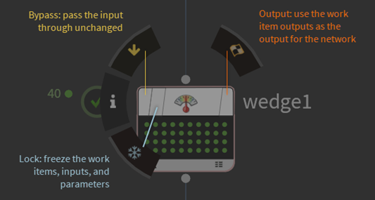
Bypass disables the node, making it pass its channels through to the output unchanged. This is useful for testing and visualizing the effect the node is having in the viewport or on the output. When a node is bypassed, the flag on the left of the node is lit yellow. |
|
T |
Output sets this node’s output as the output of the TOP network. When the output flag is on, the flag on the right of the node is lit orange and an orange ring appears around the node. |
|
None |
Lock freezes the node’s work items so that they no longer update due to input or parameter changes. This prevents any changes to the work items.
When a node is locked, the flag second from the left on the node appears red and a snowflake-shaped badge appears next to the node. 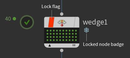
|
TOP badges 
Icon |
Meaning |
Description |
|---|---|---|
|
Node is dynamic |
When a TOP node is dynamic, a purple badge appears on the node. In TOPs, there are two types of nodes: static and dynamic. Static nodes can generate their work items without any inputs as they are not dependent on any upstream data. Dynamic nodes on the other hand require information from their inputs upstream to generate their work items. That is why dynamic nodes can only generate work items once they are cooking. To learn more about about static and dynamic TOP nodes and their significance in a TOP network, see Static vs. Dynamic. |
|
Node is locked |
This node’s work items are frozen or locked. See the Lock flag on the TOP node. |
|
Node is a locked HDA |
This node is a locked (synced) digital asset. |