| On this page |
Old network
As of Houdini 20.5, use Copernicus nodes instead of Compositing nodes. Though both networks still exist, the Compositing network is now designated as COP Network - Old. The Compositing network and its nodes will be deprecated and then removed in a future Houdini release.
Lens effects are very common and add extra realism or an artistic touch to images. Typical effects are lens distortion, chromatic aberration, vignetting and blur. The examples below provide workflows for distortion and vignetting.
Lens distortion 
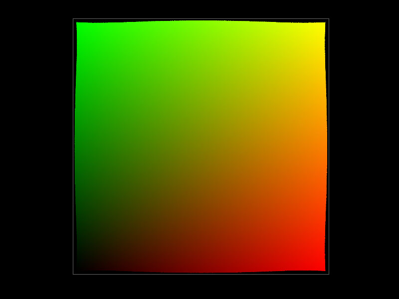
Lens distortion uses a so-called ST map. ST maps are images where every pixel has a unique red and green color. The colors correspond to the screen space’s X and Y coordinates. An ST map is the default state of the ![]() UV Map COP node.
UV Map COP node.
The following example doesn’t calculate a physically correct distortion from a real lens. The workflow only shows how to use an ST map for distortion effects. ST maps are typically provided by the matchmover or the lens manufacturer.
-
On the obj level, create a
 COP2 Network and double-click it to dive inside.
 -
Inside the network, create an UV Map COP. This node represents the ST map.
-
On the Image tab, change Override Size, e.g. to
1024, 1024. -
From the Image Planes dropdown, choose P (xyz).
-
Set Raster Depth to 32 Bit Floating Point.
-
Add a
 File COP2.
 -
Go to File and load the image you want to distort. The image in this example is a checker board and is shipped with Houdini. If you want to use this image as well, enter
$HFS/houdini/pic/CheckerBoard.pic.
Distortion image 
Houdini requires a shape to calculate the amount of distortion for each pixel of the source image. You can use another image or a simple pattern like a circle, but also more complex geometry, for example a star.
-
Add a
 Shape COP2. This node defines the distortion shape.
 -
On the Shape tab, open the Shape Type dropdown and choose Circle.
-
Go to the Image tab. For Override Size enter the same values as on the UV Map COP2. There it was
1024, 1024. -
A
 Transform COP2 node scales the circle. Add the node and connect its first input with the output of
 shape1. -
On the Transform tab you can find the Scale parameter. Set the values to
1.3, 1.3. Now, only the edges remain black. -
Add a
 Blur COP2 to soften the circle and avoid hard edges. Connect its first input to the output of
 xform1. -
On the Blur tab, set Size to
500. This value creates a very soft shape.
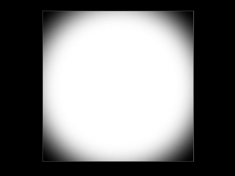
This is how the distortion image should look.
Deformation 
The next step calculates the checker board’s distortion. This step requires two deformations. The first node uses the resized and blurred shape to deform the ST map. A second node uses the ST map’s deformed pixel coordinates to deform the checker board image.
-
Add the first
 Deform COP2. Connect its first input with the output of
 uvmap1. The second input is linked to theblur1node’s output. -
Open the Deform tab and go to Deform Plane. In this node, the entry is
C. This corresponds with the UV Map’s Image Planes parameter. -
from the Deform dropdown, choose Shift by UV Gradient to use the UV/ST map’s color values to calculate the amount of distortion per pixel.
-
Scale determines the amount of distortion. Enter
2.5, 2.5to get a visible effect.The second Deform COP2 brings everything together and perform the actual calculation.
-
Add the second Deform COP2. Connect its first input with the output of the File COP2 with the checker board image. The second input is linked to the first Deform node’s output.
-
This node deforms the
Pplane of the checker board. On the Deform tab, go to Deform Plane and enterP. -
Set Deform to To New UV Values to transfer the ST map’s pixel coordinates.
-
From the Image Wrap dropdown, choose Clamp. This clamps the incoming UV values at 0 or 1.
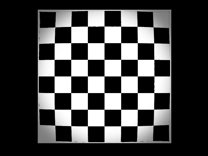
The image below shows the final effect on the checker board.
Lens vignetting 
Vignettes are caused by a loss of lens efficiency towards a the edges of a lens. Most lenses are spherical and therefore, vignettes are typically circular. But, you normally notice a stronger effect along the shorter side of the frame: the film gate’s rectangular shape fits inside the circle and the shorter side is closer to the edge of the lens. For anamorphic lenses, you can squeeze the vignette accordingly.
-
On the obj level, create a
COP2 Network and double-click it to dive inside. -
Add a
File COP2. -
Go to File and load the image you want to distort. The image in this example is a checker board and is shipped with Houdini. If you want to use this image as well, enter
$HFS/houdini/pic/CheckerBoard.pic.
The vignette 
The lens determines the vignette’s shape and in most cases it’s a circle.
-
Add a
Shape COP2. This node defines the vignette’s shape. -
On the Shape tab, open the Shape Type dropdown and choose Circle.
-
Go to the Image tab. For Override Size enter the same values as on the UV Map COP2. There it was
1024, 1024. -
From the Raster Depth dropdown, choose 32 Bit Floating Image.
-
A
Transform COP2 node scales the circle. Add the node and connect its first input with the output of shape1. -
On the Transform tab you can find the Scale parameter. Set the values to
1.05, 1.05to make the circle/vignette slightly bigger. -
Add a
Blur COP2 to soften the circle and avoid hard edges. Connect its first to input the output of xform1. -
On the Blur tab, set Size to
300.Cropping cuts away the enlarged parts of the circle and creates a clean vignette.
-
Add a
 Crop COP2 and connect its input with the output of
 blur1. -
From the Crop dropdown, choose By Offset, Width & Height.
-
Set Units to Pixels.
-
The values for Horizontal Crop and Vertical Crop must cover the entire image area. In this example, the checker board’s size is
1024by1024. The corresponding crop values are therefore0, 1024for both parameters.
What you have now is a blurred white circle on a black background.
Applying the vignette 
You can now add the blurred circle shape to the checker board image to create vignette effect.
-
Add a
 Color Correct COP2 node. Connect its first input with the output of the checker board’s File node. The second input is linked to the
 crop1node. -
At the moment you can’t see any effect. To combine vignette mask and image, you must multiply the images. On the
colorcorrect1node’s Color Correct tab and go to Master ▸ Mult. To see the vignette, set the RGB values to0.2, 0.2, 0.2, for example. What you get is a large dark area with bright edges. -
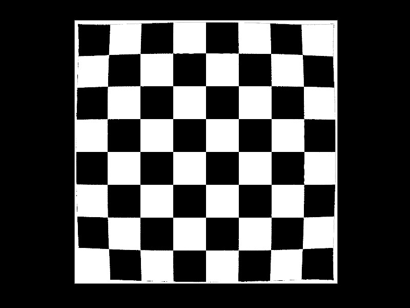
To fix the colors, open the Mask tab and turn on Invert Mask.
Below you can see the result from the example’s values and images.