| On this page |
Overview 
Vortex filaments are a way to simulate a fluid using particles. It models internal velocity using polygonal curves represent vortex centers, instead of storing velocity on a grid. Since the vortex filaments control the fluid motion, you can increase the number of particles without affecting the fluid’s behavior.
You can use the filament workflow to create the look of intricate fluid motion, such as cigarette smoke. The filament particle simulation is not necessarily realistic, but can create certain specific effects much faster than a full high-resolution fluid simulation, and with more artistic control.
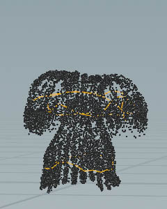
Filaments are closed polylines (polygonal curves) that represent vortex forces. The general filament setup works like this:
-
Create a geometry network to create the filament geometry.
-
Import the filament geometry into the simulation network using the
 Source Filaments node.
 -
The
 Filament Solver node advects the points of the filaments to make them drift through space.
 -
While the Filament solver moves the filaments, the
 POP Advect by Filaments node applies vortex forces to surrounding particles, making them swirl around nearby filaments.
Tip
Since it’s just polylines and particles, you could also experiment with different starting filament geometry, filament size, filament velocity attributes, and different particle treatments, to see what kind of interesting effects they create. This might be useful, for example, to create the look of a magic spell or alien device.
Using Vortex Filaments 
The ![]() Vortex Filaments shelf tool creates a filament rig using the
Vortex Filaments shelf tool creates a filament rig using the ![]() Source Filaments,
Source Filaments, ![]() POP Advect by Filaments DOP, and
POP Advect by Filaments DOP, and ![]() Filament Solver DOP nodes.
Filament Solver DOP nodes.
-
On obj level, press ⇥ Tab to invoke the TAB menu and create a
 Circle SOP. You can also draw a curve, but make to create a closed polyline. These “filament” curves will be the centers of the vortices in the simulation. Double click the Circle node to dive into it.
 -
Select the
circle1node and increase Divisions to25to get more structures. -
From the Orientation drop-down, choose ZX Plane.
-
Make sure you change the Primitive type of the curve to “Polygon”.
-
Add a
 Mountain SOP and connect it with the upstream
 circle1node. -
Under Noise Value, go to Amplitude and enter
0.5to roughen the line. -
Go to the Animation subpane and turn on Animate Noise to animate the circle’s points.
-
Add a
 Reverse SOP to make the smoke rise. Connect its input with the Mountain’s output.
The circle will be used as a particle source and to shape the particles to create the vortex rings.
-
Return to obj level and select the
circle1Geometry node. -
Open the Particles shelf tab and create a particle system using the
 Source Particle Emitter shelf tool.
 -
The tool creates a
 Dop Network Object and dives into it. You can also see particles on the circle’s surface.
 -
Again, return to obj level. With
circle1selected, click the Vortex Filaments tool on the Particles shelf tab. -
The tool dives into another network. Use the Network Editors pane’s history dropdown menu at the end of the path gadget to quickly dive into the
AutoDopNetwork.
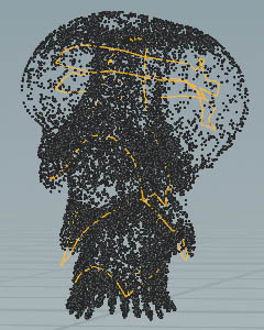
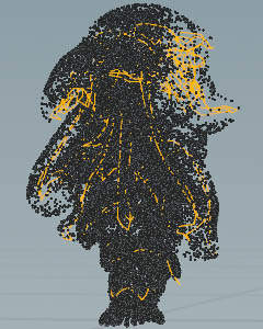
The current setup creates a single smoke plume, but following particles gather near the circle. Goal is to create reoccurring smoke puffs.
-
Select the
sourcefilaments_circle1node. -
 click the Activation parameter. From the menu, choose Delete Channels.
 -
Then, enter
$F % 20 == 1. This expression is a so-called modulo function. When the current frame, divided by20, returns1, new particles are sourced. -
Select the
gravity1node and turn off the yellow Bypass flag to deactivate it.
Finally, on the Playbar, click the ![]() icon to start the simulation. You can see the rising particles, but also how the deformed filaments are shaping the vortices.
icon to start the simulation. You can see the rising particles, but also how the deformed filaments are shaping the vortices.
Tip
The Advect by Filaments example demonstrates how to set up a filament geometry network, and how to use the dynamics nodes to create a turbulent smoke effect. Note that the file’s setup is slightly different from this workflow guide.
Important parameters 
Use Scale Strength and Scale Thickness on the ![]() Source Filaments DOP node to adjust the effect of each filament.
Source Filaments DOP node to adjust the effect of each filament.
Advanced 
-
Velocity (
v) attributes on the points of the filament curves will affect their motion. -
You can cache the filament simulation to disk as a separate pass and then read it off disk.
| See also |