| On this page |
About this tutorial 
In Houdini, you can use ![]() TOP nodes (task operators) to generate work items (tasks) to do work for you or store information. With a TOP node network, you can create a scalable recipe for generating work items, running them locally or on a farm, establishing the network of dependencies between all the work items, and figuring out how to do it all as efficiently as possible. This recipe is called a PDG (Procedural Dependency Graph).
TOP nodes (task operators) to generate work items (tasks) to do work for you or store information. With a TOP node network, you can create a scalable recipe for generating work items, running them locally or on a farm, establishing the network of dependencies between all the work items, and figuring out how to do it all as efficiently as possible. This recipe is called a PDG (Procedural Dependency Graph).
In this tutorial, you will learn how to create a linear TOP network that chains together geometry with renders and compositing, and then collects all the final frames into an MP4. And to keep things simple, you will not need to use script nodes or perform any complicated network branching. This tutorial is a good foundation for learning all the fundamental concepts of PDG before moving on to more complicated set-ups.
Tip
To learn more about about TOPs & PDG, see Intro to TOPs.
Prerequisites 
-
No prior PDG knowledge.
-
Basic understanding of FX in Houdini.
-
Some experience creating FX networks with SOPs, DOPs, and ROPs.
What you will learn 
-
General PDG concepts.
-
Most commonly used TOP nodes.
-
Basic TOP network set-up and PDG workflow for FX.
Before you begin 
Install FFmpeg 
At the end of this tutorial you will learn how to assemble all your rendered frames into a movie. To do this, you will use the ![]()
![]() FFmpeg Encode Video TOP node.
FFmpeg Encode Video TOP node.
To be able to use the FFmpeg Encode Video node, you need to have the FFmpeg utility installed on your local system.
-
Verify whether or not FFmpeg it is installed on your system by doing the following:
Mac
In a terminal shell, type
ffmpeg, and then press Enter.Windows
In a Command Prompt, type
ffmpeg, and then press Enter.Linux
In a command shell, type
ffmpeg, and then press Enter.If anything but an error is returned, then FFmpeg is installed on your system and you can move on to step 3.
-
If FFmpeg is not currently installed on your system, then you can download its installer from here.
-
Install FFmpeg.
-
-
(Windows only) Once you are sure that FFmpeg is installed on your system, verify that FFmpeg is in your system’s path.
Windows
-
Open the Edit the system environment variables control panel.
-
In the System Properties window, click Environment Variables.
-
In the Environment Variables window, select System variables > Path and then click Edit.
-
In the Edit environment variable window, scroll through the list and locate the install directory for FFmpeg.
If FFmpeg is missing from the list, then click New, type or paste the path to your local FFmpeg install folder, and then click OK.
-
Copy over the tutorial HIP file 
Before you begin, copy the Houdini HIP file that you will be working with throughout this tutorial:
-
Open a file browser window and then navigate to your Houdini install directory.
-
In the install directory, navigate to the
$HH\help\files\pdg_tutorials\intro_to_pdgfolder. -
In the
\intro_to_pdgfolder, copy thefxworkflow_tutorial.hipfile. -
Navigate to your user directory and then create a new folder named
\PDG_TUTORIAL_FILES. -
In the
\PDG_TUTORIAL_FILESworking folder, paste the HIP file. -
Run Houdini.
-
Open the
fxworkflow_tutorial.hiptutorial file and become familiar with its contents.Inside the HIP file you will find:
-
Object-context
-
Smoke Sourcing and Simulation network box
-
Source geometry for the pyro simulation (
smoke_srcSOP network). -
Pyro simulation that generates the smoke (
smoke_simDOP network). -
Output from the pyro simulation (
smoke_importSOP network).
-
-
Render network box
-
Renderable geometry for the background scene (
render_backgroundSOP network). -
Renderable pyro simulation output (
render_smokeSOP network). -
Renderable sphere (
render_sphereSOP network). -
Lights (
render_light1&render_light2). -
Camera (
render_cam).
-
-
-
Tasks-context
-
TOP network (
topnetnode)-
Local scheduler that executes your work items (
local_schedulerTOP node). -
OpenGL network that renders your frames (
opengl_renderROP network). -
COP2 network that loads in the rendered frames and assembles them into a 2×2 grid mosaic (
mosaicCOP2 network).
-
-
-
Step 1 - Define variations for the smoke 
In the first step of this tutorial you will use a ![]()
![]() Wedge TOP node to set-up a series of variations for the downstream pyro simulation (smoke) by defining the set of attributes to create variations of and the number of variations to create.
Wedge TOP node to set-up a series of variations for the downstream pyro simulation (smoke) by defining the set of attributes to create variations of and the number of variations to create.
This will allow you generate and compare variations of your smoke later on in the tutorial.
-
Run Houdini and open the
fxtutorial.hiptutorial scene file. -
In the Network Editor, navigate to the Tasks context and then dive into the
topnet1network. -
Create a Wedge node and then rename it to
smoke_variations.In the TOPs ⇥ Tab menu, you can find Wedge in the Data category.
The parameters on the Wedge node will build up percentages of attributes to change and define the number of wedges to generate.
For this tutorial, you will define a set of four different configurations for the pyro sim that will vary the force that is applied to the smoke and the size of the smoke source.
-
Select the
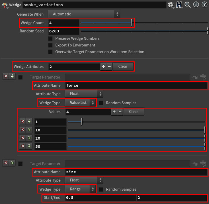
smoke_variationsnode and then configure or wedge out theforceandsizeattributes:-
Set Wedge Count to 4.
This determines the number of variations or wedges to generate.
-
Set Wedge Attributes to 2.
This determines the number of attributes to vary.
-
In the first Wedge Attributes multiparm, do the following:
-
In the Attribute Name parameter field, type
force.This allows you to vary the
forceattribute in your wedges. -
In the Wedge Type parameter drop-down menu, select Value List.
This allows you to set a specific value for the
forceattribute for each wedge. -
In the Values multiparm field, type 4.
Four Value fields appear.
-
In each Value field, type one these numbers: 1, 10, 20, and 50.
-
-
In the second Wedge Attributes multiparm, do the following:
-
In the Attribute Name parameter field, type
size.This allows you to vary the
sizeattribute in your wedges. -
In the Wedge Type parameter drop-down menu, select Range.
This allows you to set a value range for the
sizeattribute for each wedge. -
In the Start field type 0.5, and in the End field type 2.
This tells the node to pick random values, between the Start and End field values, for the
sizeattribute.
-
-
Leave all the other parameters at their default values.
-
-
Generate and cook the work items for the node.
Before a TOP node can do any work, you first need to create the tasks you want it to execute by generating the node’s work items. And to run those tasks, you need to cook the TOP node.
-
 -click on the
 smoke_variationsnode and select Generate Node from the context-sensitive menu that appears.In the Network Editor, four dots appear on the
smoke_variationsnode. Each dot represents a work item, and each work item generated by the node is a set offorceandsizeattribute variations or wedges.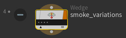
-
-click on the
smoke_variationsnode and select Cook Node from the context-sensitive menu that appears.In the Network Editor, the
smoke_variationsnode’s work item dots and status icon change color to indicate that they are being worked on, and when they have finished cooking, they change again to indicate that they have been run.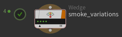
To learn more about the various TOP node UI elements, see PDG node network interface.
Each of the dots on the node now also represents a wedge.
Note
In TOPs, there are two types of nodes: static and dynamic. Static nodes can generate their work items without any inputs as they are not dependent on any upstream data. Dynamic nodes require information from their inputs upstream to generate their work items. That is why dynamic nodes can only generate work items once they are cooking.
In this tutorial,
smoke_variationsis one of many static nodes. To learn more about about static and dynamic TOP nodes and their significance in a TOP network, see Static vs. Dynamic.Tip
Cooking a node will also generate any work items on the node that need to be generated.
-
-
 -click through the work item dots on the
 smoke_variationsnode.Notice how the
wedgeindex,force, andsizeattributes change from wedge to wedge.smoke_variations work item properties Tip
You can use the [ and ] keys to step through work items on a node.
-
Save your tutorial scene.
Step 2 - Cache out the source geometry for the smoke 
In this step you will use a ![]()
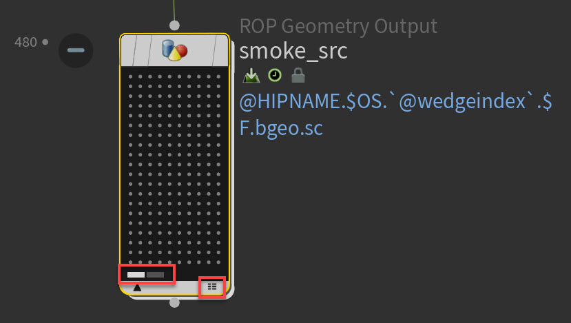
![]() ROP Geometry Output TOP node to cache out the pyro simulation’s input or source geometry for each wedge variation. The source geometry is what will emit the smoke in your scene.
ROP Geometry Output TOP node to cache out the pyro simulation’s input or source geometry for each wedge variation. The source geometry is what will emit the smoke in your scene.
This node will cache out the initial smoke point for the pyro sim and decouple the source geometry from the simulation. You want to do this so that when you change the parameter values of your simulation (like with your wedges), you do not also have to recook its source geometry. Instead, the node will just take the source geometry and run the pyro sim.
-
In the Network Editor, create a ROP Geometry Output node, rename it to
smoke_src, and then connect its input to the output of thesmoke_variationsWedge node.In the TOPs ⇥ Tab menu, you can find ROP Geometry Output in the Geometry category.
The
smoke_srcTOP node is what points to thesmoke_srcSOP network. It will generate a number of work items with the attributes you specify to cook (run) that SOP network from frames 1-120 for each wedge variation. -
Select the
smoke_srcTOP node and then configure the following parameters:-
In the Evaluate Using parameter drop-down menu, select Frame Range.
The default values for the Frame Range parameter are the
$FSTARTand$FENDvariables. These variables are built into Houdini and they correspond to the Global Animation Start Frame and Global Animation End Frame values of the Houdini playbar. So when you change the playbar’s Global Animation Frame values, the Frame Range values on thesmoke_srcTOP node will update automatically.-
Change the playbar Global Animation Frame values temporarily to see the values in the Frame Range parameter fields change accordingly.
Global Animation End Frame value affecting the node’s Frame Range End ($FEND) value -
When you have finished experimenting with the playbar’s start and end Global Animation Frame values, return those values to their defaults (1 and 120 respectively).
-
-
Specify the input path to the
smoke_srcSOP network.-
Next to the SOP Path parameter field, click the Open floating operator chooser button.
-
In the Choose Operator pop-up window that appears, select obj ▸ smoke_src ▸ create_density_volume and then click Accept.
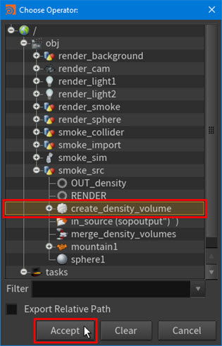
The following path appears in the SOP Path parameter field:
/obj/smoke_src/create_density_volume
The
smoke_srcTOP node now knows which geometry to use as the simulation’s source geometry. -
-
Specify the output path for the
smoke_srcTOP node.Since you are wedging out four output files for each frame (one for each wedge variation), you need to create a unique file path that includes the wedge number so that the output files do not overwrite each other.
-
In the Output File parameter field, type the following:
$HIP/geo/$HIPNAME.$OS.`@wedgeindex`.$F.bgeo.sc
wedgeindexis an attribute that is automatically created by a Wedge node. It identifies each wedge number in the wedge count.Note
If you were using nested wedging, where you have one Wedge node after another, each wedge would have a unique wedge index. The wedge number is the number from the wedge count and it comes from inside the Wedge node. The wedge index on the other hand is the globally unique index of a particular wedge variation. So the wedge number goes up in a 0,1,2,3 and so on sequence, but the wedge index starts at 0 and goes up to the number of work items. The wedge index is guaranteed to be unique.
For this tutorial, wedge number and wedge index are the same thing since you are not using nested wedging, and you should use the
@wedgeindexvariable in your output file names so that your file names are always unique.
-
-
Leave all the other parameters at their default values.
-
-
Examine the work items that are generated by your
smoke_srcTOP node.-
Generate the work items for the node.
480 dots appear inside the node. Each of these dots represent a source geometry work item for each frame of each wedge (120 frames x 4 wedges).
-
Click on some of the work item dots inside the
smoke_srcnode.Notice the lines that appear between the work items on the
smoke_variationsnode and their associated tasks on thesmoke_srcnode. These lines and their corresponding dot highlights indicate the connections between the work items.The
smoke_variationsnode generates work items to cook thesmoke_srcnode’s source geometry from frames 1-120 for each wedge variation. -
In the
smoke_variationsnode, do the following:-
Temporarily increase the Wedge Count to 5.
-
-click on the
smoke_variationsnode and select Dirty and Cook This Node from the context-sensitive menu that appears. -
Generate the work items for the
smoke_srcTOP node.
This increases the number of wedge variations because the
smoke_srcnode applies its generate frames procedure to each input work item. So instead of generating 480 frames, it now generates 600 frames. -
-
Return the Wedge Count to its original value.
-
In the
smoke_variationsnode, decrease the Wedge Count to 4. -
Dirty and recook the
smoke_variationsnode. -
Generate the work items for the
smoke_srcTOP node one last time.
-
-
View all the work items for the
smoke_srcTOP node.Notice how you cannot see all the dots for all the work items on the node.
When there are too many work items to display inside a node in the Network Editor, you can either click the bar underneath the dots or open the work item spreadsheet or Task Table Graph window.
-
Open the Task Table Graph for the
smoke_srcTOP node.To open the Task Table Graph window, click the on the two-column icon located in the bottom right-hand corner of the node.
You can use the Task Table Graph to inspect the statuses of all of the work items on the node in an easy-to-navigate and understand table format.
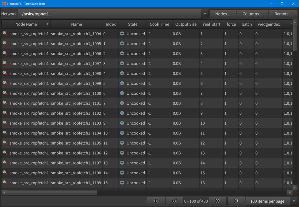
Task Graph Table for the smoke_src node work items
-
-
-
Enable batching for your
smoke_srcTOP node.-
In the
smoke_srcnode, select the ROP Fetch tab.Look at the Frames per Batch parameter.
With its current value, the node will cook and produce the output you want, but it will be inefficient at it because the node will create one process per work item. The node will cook each work item for the source geometry in a unique process done by the local scheduler, and since the network you are cooking is pretty fast to cook, a lot of time will be wasted just spawning processes and managing the scheduling of those processes instead of actually doing the work.
To speed things up, you need to increase the batch size.
-
Set the Frames per Batch parameter to 10.
A batch size of 10 means that the node will cook ten work items in each process instead of just one.
By collecting the work items to cook in this way, the node shares some of the overhead of starting up processes across multiple work items.
-
-
Cook the
smoke_srcTOP node.You will see the cook statuses of the various work items on the
smoke_srcnode appear on both the node in the Network Editor and the Task Graph Table window.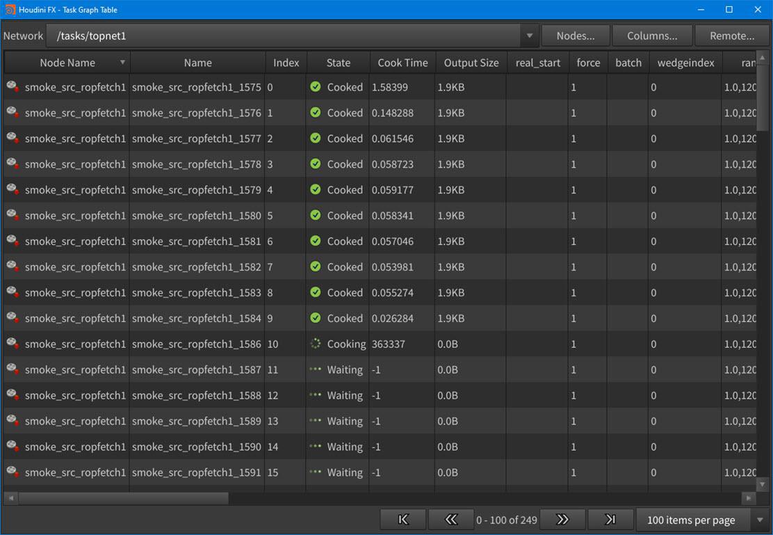
Task Graph Table window The cook statuses for all your work items also appear in the Network Editor’s tasks menu bar.
To learn more about work item dot colors and status icons, see PDG node network interface.
Note
-
Each of the dots on the
smoke_srcnode now also represents a frame of animated geometry. -
Cooking a TOP node will also cook any upstream uncooked nodes in its TOP network. In this case, if the
smoke_variationsWedge node was uncooked, then cooking thesmoke_srcTOP node would also cook thesmoke_variationsnode as it is an input.
-
-
Enable the By Batch task collapse option.
Currently, all the work items on the
smoke_srcTOP node are shown as individual dots even though they are batched work items.To reduce the number of work items you see on the node, you can turn on the By Batch task display mode.
-
In the Network Editor, select Tasks menu ▸ Task Graph Display Options.
-
In the Task Graph Display Options pop-up window, select By Batch from the Task Collapse Mode drop-down menu.
All the work item dots on the node now appear as batch work item rings. And since Frames per Batch is set to 10, each ring represents a batch of ten work items. Visualizing the work items in this way makes managing and debugging what is going on with your node’s work items a lot easier.
-
Normally you would keep this display option turned on. However, so that you can see the connections between your tasks during this tutorial, turn on Collapse ▸ Off. This will disable By Batch.
-
-
Explore the
@attribute referencing in your network.-
Switch to the Object context.
-
In the Smoke Sourcing and Simulation network box, dive into the
smoke_srcSOP network. -
Select the
sphere1node and look at the value of its Uniform Scale parameter.Notice that the sphere is referencing the
sizePDG attribute using an@variable.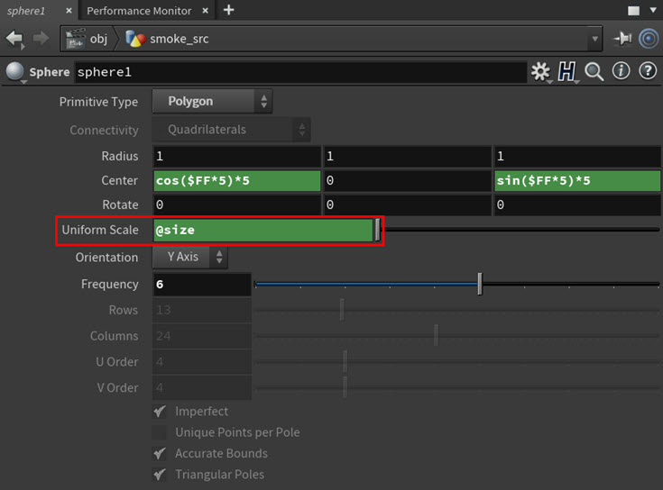
Since the
@sizevariable is an attribute on yoursmoke_variationsWedge node work items, this means that thesmoke_srcSOP network the Wedge node is pointing to has a reference to thesizePDG attribute you created, and the SOP network also knows how to use that wedge variable.This
@attribute referencing gives you a way to interactively preview what your wedge properties will look like. If you display thesmoke_srcSOP network in the viewport, then you will be able to preview your output geometry wedge variations by clicking through your wedges. Also, every time the@sizevariable changes, Houdini will refresh thesphere1node and display the new evaluation of it with respect to the wedge attribute’s new value.Note
Using
@attribute referencing to create these kinds of relationships is called pull-style wedging. To learn more about the different kinds of TOPs wedging techniques, see Pull vs. push. -
Turn on the Display flag for the
sphere1node. -
Return to the top-level Object context.
-
Turn on the Display flag for the
smoke_srcSOP network. -
Return to the Topnet context.
-
Click through the
smoke_variationswedges to preview your wedged geometry in the viewport.Smoke source geometry size variations
-
-
Save your tutorial scene.
Step 3 - Import the simulation output for the smoke 
In this step you will use a ![]()
![]() ROP Geometry Output TOP node to import and run the pyro simulation’s (smoke) output for each wedge variation.
ROP Geometry Output TOP node to import and run the pyro simulation’s (smoke) output for each wedge variation.
-
In the Network Editor, create a ROP Geometry Output node, rename it to
smoke_sim, and then connect its input to the output of thesmoke_srcTOP node.In the TOPs ⇥ Tab menu, you can find ROP Geometry Output in the Geometry category.
The
smoke_simTOP node is what points to thesmoke_importSOP network. It will generate a number of work items with the attributes you specify to cook that SOP network from frames 1-120 for each wedge variation. -
Select the
smoke_simTOP node and then configure the following parameters:-
In the ROP Geometry tab, leave the Evaluate Using parameter set to its default value, Single Frame.
You do not have to configure this parameter. Since the
smoke_simnode is wired into the inputsmoke_srcTOP node, and that node already has work items,smoke_simwill automatically generate one sim work item for each sim source work item on the input. -
Specify the SOP Path to the
smoke_importSOP network.The
smoke_simnode needs to point to the actual pyro simulation output and not just the sim source. Thesmoke_simTOP node will take the output from the simulation’s DOP network and pull it into the geometry.-
Next to the SOP Path parameter field, click the Open floating operator chooser button.
-
In the Choose Operator pop-up window that appears, select obj ▸ smoke_import ▸ import_pyrofields and then click Accept.
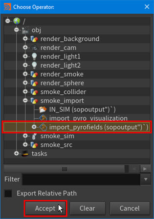
The following path appears in the SOP Path parameter field:
/obj/smoke_import/import_pyrofields
The
smoke_simTOP node now knows which simulation output to use for the smoke. -
-
Specify the output path for the
smoke_simTOP node.Just like with the
smoke_srcTOP node, you need to create a unique file path that includes the wedge number so that the output files do not overwrite each other.@wedgeindexwill allow you to create output files with unique file names.In the Output File parameter field, type the following:
$HIP/geo/$OS.`@wedgeindex`.$F4.bgeo.sc
-
-
Set up caching for your simulation.
-
In the ROP Fetch tab, select Write Files from the Cache Mode parameter drop-down menu.
This writes out the cooked simulation frames so that you can playback your wedged simulation frames in the viewport more quickly.
-
-
Examine the work items that are generated by your
smoke_simTOP node.-
Generate the work items for the node.
480 dots appear inside the node. Each of these dots represent a pyro sim work item for each frame of each wedge (120 frames x 4 wedges).
-
Click on some of the work item dots inside the
smoke_simnode.Notice the lines that appear between the pyro sim tasks on the
smoke_simnode, their associated source geometry frames on thesmoke_srcnode, and their associated wedges on thesmoke_variationsnode. These lines and their corresponding dot highlights indicates the dependencies between the node work items.Tip
PDG stores all of its file paths in a generic special format that allows it to access files stored on different platforms (Windows, Linux, and so on) on a farm. This special format uses special PDG tokens in the file paths.
-
Double-click a work item dot on the
smoke_simTOP node. -
In the Task Info pop-up window that appears, look at the paths for the Command, Input, and Output.
By default, these paths appear in a human-readable format.
-
Click the folder icon at the top of the Task Info pop-up window.
The paths now appear in their raw tokenized formats. This is how the paths are stored inside their respective attributes on the work item.
-
-
-
Cook all the
smoke_simTOP node’s work items in one batch.Since
smoke_simis importing and running a simulation, and there are dependences between simulation frames (the second frame depends on the first frame and so on), you need to cook all the node’s work items in a single process or job. You can do this with the All Frames in One Batch parameter.-
In the ROP Fetch tab, turn on All Frames in One Batch to enable batching for your
smoke_simnode.Warning
Anytime you are running a simulation, you always want to enable All Frames in One Batch. Otherwise, you run into problems with your simulation because you cannot run a simulation in multiple processes.
-
Cook the
smoke_simnode.You will see the cook statuses of the various work items on the
smoke_simnode appear on the node in the Network Editor, the Task Table Graph window, and the Network Editor’s tasks menu bar.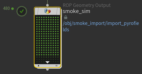
Each of the dots on the node also now represents a frame of simulation.
-
-
Explore the
@attribute referencing in your network.-
Switch to the Object context.
-
In the Smoke Sourcing and Simulation box, dive into the
smoke_simDOP network. -
Select the
uniformforce1node and look at the value of its Force parameter.Notice that the uniform force is referencing the
forcePDG attribute using the@forcewedge variable you created. That is how the simulation is pulling in theforceattribute from the wedges and making use of it.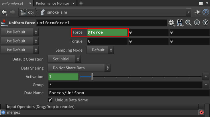
Just like with the
smoke_srcTOP node, this@attribute referencing gives you a way to interactively preview what your wedge properties will look like for the simulation. If you display thesmoke_simDOP network in the viewport, then you will be able to preview your simulation wedge variations by clicking through your wedges. Also, every time the@forcevariable changes, Houdini will refresh theuniformforce1node and display the new evaluation of it with respect to the wedge attribute’s new value. -
Turn on the Output flag for the
uniformforce1node. -
Return to the top-level Object context.
-
Turn on the Display flag for the
smoke_simDOP network. -
Return to the Topnet context.
-
Playback your simulation and click through the
smoke_variationswedges to preview your wedged simulations in the viewport.
Smoke simulation force variations -
-
Save your tutorial scene.
Step 4 - Filter out the frames that do not contain the smoke 
In this step you will use a ![]()
![]() Filter by Range TOP node to filter out the first few frames of your simulation.
Filter by Range TOP node to filter out the first few frames of your simulation.
The pyro sim output that the smoke_sim TOP node imports is not very noticeable until around frame 25. Filtering out the frames that appear almost empty will trim the upstream frame range so that downstream nodes (like the render nodes) will only have to work on a subset of the input frame range. This way the pyro sim will have a large volume of smoke right from the beginning of its simulation, and the downstream renderers will get to start with some actual smoke in the scene.
-
In the Network Editor, create a Filter by Range node, rename it to
render_range, and then connect its input to the output of thesmoke_simTOP node.In the TOPs ⇥ Tab menu, you can find Filter by Range in the Data category.
-
Select the
render_rangenode and then configure the following parameters:-
In the first Filter Range parameter field, type 25.
This sets frame 25 as the first frame of the simulation frame range.
-
In the last Filter Range parameter field, type the
$FENDvariable.This sets the current Global Animation Frame Range value as the last frame of the simulation frame range.
-
-
Generate the
render_rangenode.Notice how the number of work items items on the node is 384. This is because the first 25 frames of each wedge variation have been excluded by the
render_rangenode (96 frames x 4 wedges). -
Click on the first work item dot in the
smoke_simTOP node.Notice how a dependency line does not appear between the work item dot you clicked on and any of the
render_rangenode work items. That is because the frame you clicked on was trimmed by therender_rangenode, and consequently a work item was not generated for it. If you select an item dot further in the node you see a dependency line. -
Cook the
render_rangenode. -
-click through the work item dots on the
render_rangenode.Notice how the
rangeattribute has changed to25.0, 120.0, 1.0to reflect the new range of frames for the output.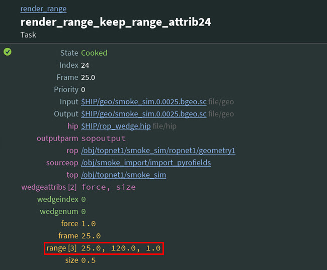
Tip
You can use the [ and ] keys to step through work items on a node.
-
Save your tutorial scene.
Step 5 - Render out the smoke 
In this step you will use two ![]()
![]() ROP Fetch TOP nodes, one high-quality and the other low-quality, to render out your pyro simulation (smoke) frames for each wedge variation using GPU openGL.
ROP Fetch TOP nodes, one high-quality and the other low-quality, to render out your pyro simulation (smoke) frames for each wedge variation using GPU openGL.
Since Houdini does not have openGL TOP render nodes, these nodes will point to two already established openGL ROP networks. Also, since openGL can only work in a local graphical session of Houdini, you will only be rendering locally (not on the farm) for this tutorial.
Tip
-
Even though the ⇥ Tab menu for TOPs does not support all ROPs, you can still use a ROP Fetch TOP node to point to any node that behaves like a ROP. For example, like a
 Vellum I/O node or a
  File Cache node.
 -
If you are interested in rendering on a farm, raytracing, or using USD, you can always use the
 ROP Mantra Render TOP node (Mantra renderer that supports raytracing) or the
  USD Render TOP node (Karma renderer that supports USD and LOPs) in your own set-ups outside this tutorial.
-
In the Network Editor, create a ROP Fetch node, rename it to
gl_render, and then connect its input to the output of therender_rangenode.In the TOPs ⇥ Tab menu, you can find ROP Fetch in the Render category.
This will be your high-quality openGL render node.
-
Select the
gl_rendernode and then configure the following parameters:-
Specify the input path to the high-quality openGL ROP network.
-
Next to the ROP Path parameter field, click the Open floating operator chooser button.
-
In the Choose Operator pop-up window that appears, select tasks ▸ topnet1 ▸ opengl_render ▸ opengl and then click Accept.
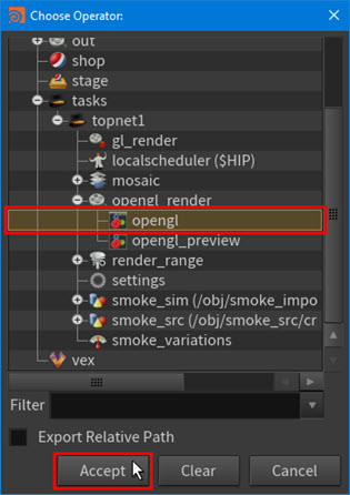
The following path appears in the ROP Path parameter field:
/tasks/topnet1/opengl_render/opengl
The
gl_rendernode now knows which ROP network to use to render the frames of your pyro sim (smoke).Note
-
You do not need to specify an output folder for your openGL rendered frames as this is already defined in the
openglROP network. -
OpenGL will use your system’s graphics card (GPU) to render your frames.
-
-
In the Frames and Batching tab, set the Frames per Batch parameter to 40.
For render nodes, you always want to run some level of batching so that you are not spending a lot of time waiting for processes to start or frames to render.
Outside this tutorial, the batch size you choose should depend on your hardware and the nature of the job you are cooking. If you set the batch size too large, then your cook will not be very efficient because you are only starting a couple of processes and it will take a long time to do a lot of work. If you set the batch size too small, then you will pay too much cost based on process overhead.
Tip
A good rule for choosing a batch size is as follows: set your batch size to the
# of work itemsdivided by the# of cores on your render machine. For example, if you have 24 cores, then ideally you would want 24 processes (one process per core).
-
-
Select the
gl_rendernode, press ⌃ Ctrl + c, and then press ⌃ Ctrl + v.A new duplicate render node named
gl_render1appears in the Network Editor, and its input is already connected to the output of therender_rangenode.-
Select the
gl_render1node and rename it togl_render_preview.
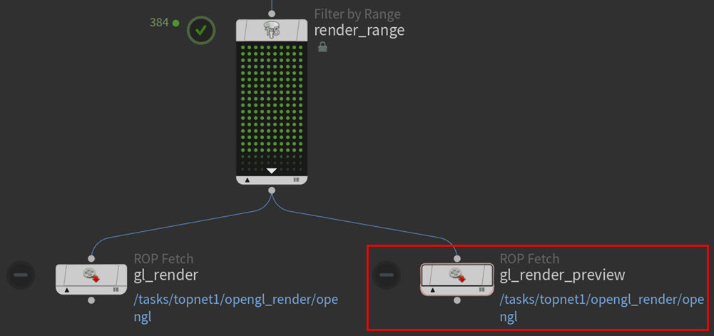
This will be your low-quality openGL render node.
-
-
Select the
gl_render_previewnode and then configure the following parameters:-
Specify the input path to the low-quality OpenGL ROP network.
-
Next to the ROP Path parameter field, click the Open floating operator chooser button.
-
In the Choose Operator pop-up window that appears, select obj ▸ topnet1 ▸ opengl_render ▸ opengl_preview and then click Accept.
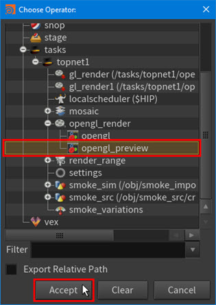
The following path appears in the ROP Path parameter field:
/obj/topnet1/opengl_render/opengl_preview
The
gl_render_previewTOP node now knows which ROP network to use to render the frames of your pyro sim (smoke).Note
You do not need to specify an output folder for your openGL rendered frames as this is already defined in the
opengl_previewROP network. -
-
In the Frames and Batching tab, set the Frames per Batch parameter to 20.
-
-
Cook the
gl_renderandgl_render_previewnodes one at a time.Dots appear inside each of the nodes. Each of these dots represent render work items for each filtered frame of each wedge (96 frames x 4 wedges).
Note
Cooking a node will also generate any work items on the node that need to be generated.
The preview openGL renderer will cook your work items fairly quickly, but the higher quality openGL renderer will take a little more time to cook.
You will see the cook statuses of the various work items on the
gl_renderandgl_render_previewnodes appear on the nodes in the Network Editor, the Task Table Graph window, and the Network Editor’s tasks menu bar.Once your render nodes are cooked, you will have your final rendered frames.
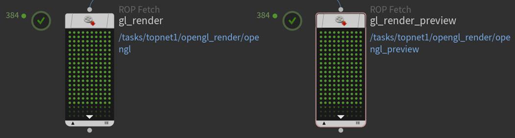
Cooked gl_render and gl_render_preview nodes -
Look at your rendered frames.
-
View the node info for the
gl_rendernode and then select the Output.exrlink.The
opengl.exrvideo appears in MPlay. -
View the node info for the
gl_render_previewnode and then select the Output.exrlink.The
opengl_preview.exrvideo appears in MPlay. -
Playback both the
.exrvideos and compare the render results.Notice how the
opengl.exrvideo is higher quality than theopengl_preview.exr.gl_render EXR video gl_render_preview EXR video
-
-
Save your tutorial scene.
Step 6 - Set up a switch for the renderers 
In this step you will use a ![]()
![]() Switch TOP node to set up a toggle that will allow you to choose which input renderer,
Switch TOP node to set up a toggle that will allow you to choose which input renderer, gl_render (high-quality) or gl_render_preview (low-quality), to use in your TOP network.
Tip
-
Adding this switch will split your network into two branches. Outside this tutorial, this is very useful for production situations that may require you to output your frames at different resolutions (for example, like for your own review, for rounds, or for dailies).
-
Even though the Switch node will only cook one of your TOP network’s branches, you can still manually cook any of your TOP render nodes.
-
In the Network Editor, create a Switch TOP node, rename it to
select_render, and then connect its input to the outputs of thegl_renderandgl_render_previewnodes.In the TOPs ⇥ Tab menu, you can find Switch in the Utility category.
The
select_rendernode now determines which renderer to use and which branch to cook for your TOP network.Connecting the
select_rendernode to the render nodes removed the work items from one of your render nodes.-
Recook the render node that no longer has work items.
-
-
Select the
select_rendernode and look at its parameters.The node’s inputs appear as selectable input operators in its parameter settings.
Each input is assigned a Select Input number based on their order in the Input Operators list. For your
select_rendernode,gl_renderis input 0 andgl_render_previewis input 1. -
With the Select Input slider, switch back and forth between the
gl_renderand thegl_render_previewinputs and watch what happens in the Network Editor.Notice how the line that connects the
select_rendernode to the openGL render nodes appears solid when a renderer is selected and dotted when a renderer is not selected. The current active render node in your TOP network is the node connected to theselect_rendernode with a solid line.Note
-
When you switch between renderers, you will need to recook the downstream nodes for the renderer branch you switched to if those nodes have not been previously cooked.
-
Switching renderers does not dirty the upstream nodes if those nodes have been previously cooked.
-
-
Set the
select_rendernode’s input operator to thegl_render_previewnode.For the rest of this tutorial, you will be working with the
gl_render_previewnode’s rendered frames. -
Save your tutorial scene.
Step 7 - Apply captions to the rendered frames 
In this step you will use a special preconfigured ![]()
![]() ROP Composite Output TOP node named Overlay Text to layer caption text on top of your rendered frames. This text will provide important wedge variation information about each frame like their frame numbers,
ROP Composite Output TOP node named Overlay Text to layer caption text on top of your rendered frames. This text will provide important wedge variation information about each frame like their frame numbers, Force values, and Size values.
This kind of overlay is a helpful visual reference when you are reviewing and comparing your wedge variations (for example, like frame 50 from four different wedge variations). It will help you quickly identify the settings that were used to produce a frame you like and it is also very useful information to have on hand when you are debugging your FX.
-
In the Network Editor, create an Overlay Text node, rename it to
wedge_overlay, and then connect its input to the output of theselect_rendernode.In the TOPs ⇥ Tab menu, you can find Overlay Text in the Images category.
-
Select the
wedge_overlaynode and then configure the following parameters:-
In the Overlay tab, type the following expression into the Text field:
Frame: $F3
Size: `@size`
Force: `@force`
$F3is the frame number up to 3 digits,@size(using the@operator you have seen before) is referencing thesizewedge work item attribute, and@forceis referencing theforcewedge work item attribute.This expression is evaluated for each work item. It takes in an input render frame, evaluates the attributes on that frame’s work item, and then figures out what text to layer on top of the render frame.
-
In the ROP Composite tab, type the following into the Output Picture parameter field:
$HIP/comp/$HIPNAME.$OS.`@wedgeindex`.$F4.exr
-
In the ROP Fetch tab, turn on All Frames in One Batch.
This node usually benefits from batching. But in this tutorial, since this COP node will cook at almost interactive speeds, you do not need to use Frames per Batch.
-
-
Cook the
wedge_overlaynode.Dots appear inside the node. Each dot represents an overlay image work item for each rendered frame of each wedge (96 frames x 4 wedges).
Once the
wedge_overlaynode is cooked, you will have your composited overlay images. -
Look at your overlay frames.
-
View the node info for the
wedge_overlaynode and then select the Output.exrlink.The
fxtutorial.wedge_overlay.exrvideo appears in MPlay. -
Playback the
fxtutorial.wedge_overlay.exrvideo.Notice the text captions in the video.
-
-
Save your tutorial scene.
Step 8 - Collect and organize the overlay images 
In this step you will use a ![]()
![]() Partition by Frame TOP node to collect and organize the input overlay images into buckets or partitions.
Partition by Frame TOP node to collect and organize the input overlay images into buckets or partitions.
Your overlay images need to be organized by frame number before you can pass them on to the mosaic node you will be creating in Step 9.
-
In the Network Editor, create a Partition by Frame node, rename it to
collect_frames, and then connect its input to the output of thewedge_overlaynode.In the TOPs ⇥ Tab menu, you can find Partition by Frame in the Partitioner category.
-
Leave the
collect_framesnode’s parameters as their default values.You do not need to change any of the parameter settings on this node.
-
Cook the
collect_framesnode.The
collect_framesnode generates its work items for all the overlay images and puts them into partitions based on frame number. Each partition has four work items, one from each of the wedge variations.96 small rectangles also appear in the node (384 overlay images / 4 wedges).
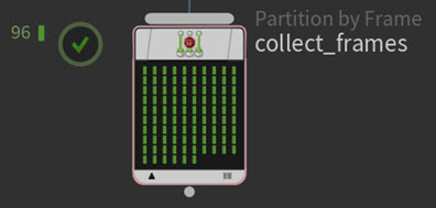
The
collect_framesgathers the overlay images into its partitions.Each
collect_frameswork item only finishes cooking when all four of its like-numberedwedge_overlayimages complete cooking. -
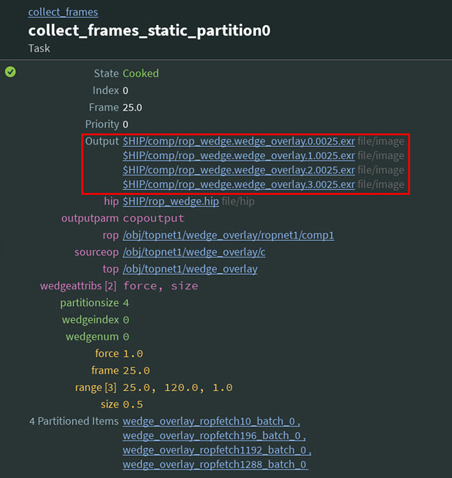
-click through the work item dots on the
collect_framesnode.Look at the Output of each work item. Notice how the node has grouped 4 frames—the same frame from each of the wedges—in each partition.
Tip
You can use the [ and ] keys to step through work items on a node.
-
Save your tutorial scene.
Step 9 - Assemble the partitioned overlay images into 2×2 mosaic images 
In this step you will use a ![]()
![]() ROP Composite Output TOP node to assemble or
ROP Composite Output TOP node to assemble or ![]() composite all four wedge variations of an overlay image for each frame number into 2×2 grids or mosaics.
composite all four wedge variations of an overlay image for each frame number into 2×2 grids or mosaics.
Note
If you are using Houdini Apprentice, the maximum resolution you can render is 1280×720. See Houdini Apprentice restrictions for more information.
These mosaics will allow you to compare each of your frames for each of your wedges. For example, the mosaic will let you compare each frame 50 from all four of your wedges.
-
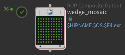
In the Network Editor, create a ROP Composite Output node, rename it to
wedge_mosaic, and then connect its input to the output of thecollect_framesnode .In the TOPs ⇥ Tab menu, you can find ROP Composite Output in the Render category.
-
Select the
wedge_mosaicnode and then configure the following parameters:-
In the ROP Composite tab, turn on the Use External COP parameter in the Composite tab.
-
Next to the COP Path parameter field, click the Open floating operator chooser button.
-
In the Choose Operator pop-up window that appears, select tasks ▸ topnet1 ▸ mosaic ▸ mosaic1 and then click Accept.
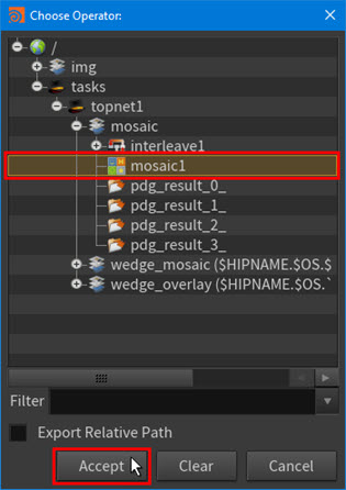
The following path appears in the COP Path parameter field:
/tasks/topnet1/mosaic/mosaic1
The
wedge_mosaicnode now knows which COP network to use to load in and composite the overlay images. -
-
Leave the Output Picture parameter value at its default value.
Since this node is going to take all four variations of the overlay image and then turn them into a single image, you no longer need to use the
@wedgeindexvariable in the output path for your node. -
In the ROP Fetch tab, set the Frames per Batch parameter to 5 in the Frames and Batching tab.
The
wedge_mosaicnode will benefit from a little bit of batching as it is more expensive than the other COP-type node (wedge_overlay) in your network.
-
-
Cook the
wedge_mosaicnode.96 dots appear inside the node. Each dot represents a mosaic image work item (384 overlay images / 4 wedges).
The
wedge_mosaicnode takes the overlay images from each partition and stitches them together into single composite 2×2 grid images. -
Look at your mosaic images.
-
View the node info for the
wedge_mosaicnode and then select the Output.exrlink.A video of your output mosaic images appears in MPlay.
-
Playback the
fxtutorial.wedge_mosaic.exrvideo.Notice that the video contains all your 2×2 mosaic images arranged in sequential order by frame number.
-
-
Save your tutorial scene.
Step 10 - Collect all the mosaic images 
In this step you will use a ![]()
![]() Wait for All TOP node to collect all of the input mosaic images in a single partition.
Wait for All TOP node to collect all of the input mosaic images in a single partition.
You need to have all the completed composite mosaic images before you can pass them on to the video node you will be creating in step 11.
-
In the Network Editor, create a Wait for All node, keep the default
waitforall1name, and then connect its input to the output of thewedge_mosaicnode.In the TOPs ⇥ Tab menu, you can find Wait For All in the Dependencies category.
-
Cook the
waitforall1node.The node’s single work item appears as a rectangle on the node.
The node collects all the mosaic images into a single partition and the node’s single partition appears as a rectangle on the node.
The
waitforall1node will wait for all the compositing from thewedge_mosaicnode to complete before passing on the mosaic images to the downstream FFmpeg Encode Video node.This is important because the video node needs all the composite mosaic images before it can generate and output its movie.
-
Save your tutorial scene.
Step 11 - Turn the mosaic images into a movie 
In this final step you will use an ![]()
![]() FFmpeg Encode Video TOP node to assemble all the mosaic images being held by the
FFmpeg Encode Video TOP node to assemble all the mosaic images being held by the waitforall1 node into a single MP4 video.
Note
To be able to use the FFmpeg Encode Video node, you need to have the FFmpeg utility installed on your local system. For more information about verifying the FFmpeg installation or installing the utility, see Install FFmpeg.
-
In the Network Editor, create an FFmpeg Encode Video node, rename it to
make_movie, and then connect its input to the output of thewaitforall1node.In the TOPs ⇥ Tab menu, you can find FFmpeg Encode Video in the Images category.
-
Leave the
make_movienode parameter settings as their defaults. -
Cook the
make_movienode.The node’s single work item appears as a dot on the node.
The
make_movienode takes all the composite mosaic images in thewaitforall1partition, assembles them into a movie, and then outputs them as an MP4 video file. -
Take a look at your final MP4 video.
-
View the node info for the
make_movienode and then select the Output.mp4link.The
make_movie_#.mp4video containing your network’s final output appears in your local, default video player.
-
-
Save your tutorial scene.
Congratulations! You have completed the FX Workflow PDG tutorial.
If you would like to see what your final TOP network should look like, see the rop_wedge.hip example file located in your Houdini example file directory ($HH\help\files\pdg_examples\top_rop\).
To continue learning about PDG workflows, you can step through the other beginner tutorials in this Houdini docs series or visit the Pipeline|PDG Learning Path on our website.