| On this page |
The high-level tool for pre-fracturing geometry is the ![]() RBD Material Fracture SOP, which allows you to accurately fracture geometry based on a specific type of material. Concrete is the default Material Type on this node.
RBD Material Fracture SOP, which allows you to accurately fracture geometry based on a specific type of material. Concrete is the default Material Type on this node.
Pre-fracturing 
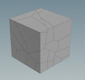
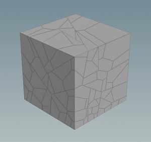
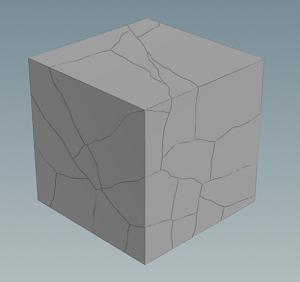
Concrete fracturing uses a Voronoi fracture approach, with more options for getting higher resolution geometry. The Fracture Level will control how many cuts your object will have. Increasing this number will add more fractures to the existing fractured pieces, breaking each chunk into smaller pieces. The image on the left shows a Fracture Level of 2 and the image on the right shows a fracture level of 3. The Primary Strength parameter on the Constraints tab controls the how strongly the fractured pieces hold together.
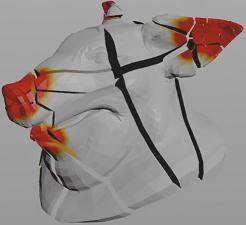
The first fracture level works like the ![]() Shatter shelf tool, which takes a volume, scatters points, and applies a Voronoi fracture. You can see this more clearly by changing the Guide Geometry to Primary Volume to visualize. For example, if you set the Noise Frequency to
Shatter shelf tool, which takes a volume, scatters points, and applies a Voronoi fracture. You can see this more clearly by changing the Guide Geometry to Primary Volume to visualize. For example, if you set the Noise Frequency to 0, you’ll get uniformly scattered points, which results in a typical Voronoi fracture with similar sized chucks. However, the Noise Frequency and Noise Offset parameters can vary the density throughout the volume. The red areas indicate areas of higher density and black areas indicate areas of lower density, which in turn determines where the points are scattered. This helps you get more interesting shapes by default, instead of uniformly shattered pieces.
If you have multiple fracture levels, the Fracture Ratio and Fracture Seed will determine how many pieces from the previous level to fracture.
You can also use the ![]() RBD Paint node to interactively paint weaker areas on the geometry in the viewport before the
RBD Paint node to interactively paint weaker areas on the geometry in the viewport before the ![]() RBD Material Fracture node. This will paint a
RBD Material Fracture node. This will paint a density attribute in the areas you want more fracturing to occur.
Chipping 
Enable Chipping on the Chipping tab will make your simulation more realistic looking, as it will break off the corners and round off the concrete pieces as they break apart.
Understanding Chipping parameters 
The chipping parameters can give you a lot of control over the look of the chipped pieces.
| To... | Do this |
|---|---|
|
Control how many pieces get chipping applied |
Increase or decrease the Chipping Ratio parameter. A value of |
|
Determine how many of the corners get chipping applied |
Adjust the Corner Ratio. A value of |
|
Regulate how big the chips are |
Modify the Corner Depth parameter to control how big the chips will be relative to the center of the piece. Increasing this parameter will make the chips bigger. |
|
Provide variation in cutting planes |
Use the Directional Noise parameter. A value of |
|
Control how strongly the chipped pieces stick to the main fracture piece. |
Modify the Chipping Glue Strength on the Constraints tab. |
Details 
Turning on Edge Detail will add more noise to the cuts, making them appear more jagged along the edges. You can increase the jaggedness of the edges by increasing the Noise Height parameter.
Tip
In order to tune the detail noise settings quickly, disable Edge Detail, display the Edge Detail guide geo and edit the Noise Height, Noise Element Size, Lacunarity, and Level Multiplier parameters. Once you're happy with the results, re-enable Edge Detail.
Turing on Interior Detail will add noise and displacement to exposed interior surfaces after fracturing, which can be used to produce more interesting high resolution geometry. You can change the amplitude of the displacement by increasing or decreasing the Noise Amplitude parameter.

Proxy geometry 
By default, the ![]() RBD Material Fracture SOP uses the Voronoi fracture shapes as the proxy geometry. However, if you use Edge Detail and Interior Detail your pieces will be higher resolution and won’t match perfectly. It is usually close enough to give good results, but you have the option of using Convex Decomposition with controls for Max Concavity to get a closer match to the higher resolution pieces. Alternatively, you can use Packed Spheres with controls for Voxel Size to get a cheaper proxy set up.
RBD Material Fracture SOP uses the Voronoi fracture shapes as the proxy geometry. However, if you use Edge Detail and Interior Detail your pieces will be higher resolution and won’t match perfectly. It is usually close enough to give good results, but you have the option of using Convex Decomposition with controls for Max Concavity to get a closer match to the higher resolution pieces. Alternatively, you can use Packed Spheres with controls for Voxel Size to get a cheaper proxy set up.
Constraints 
The Constraints tab has special constraints for concrete fractures, which allow you to set the strength of the glue bonds between the levels of fractures and chipping. For more information, see the Constraints help page.