| On this page |
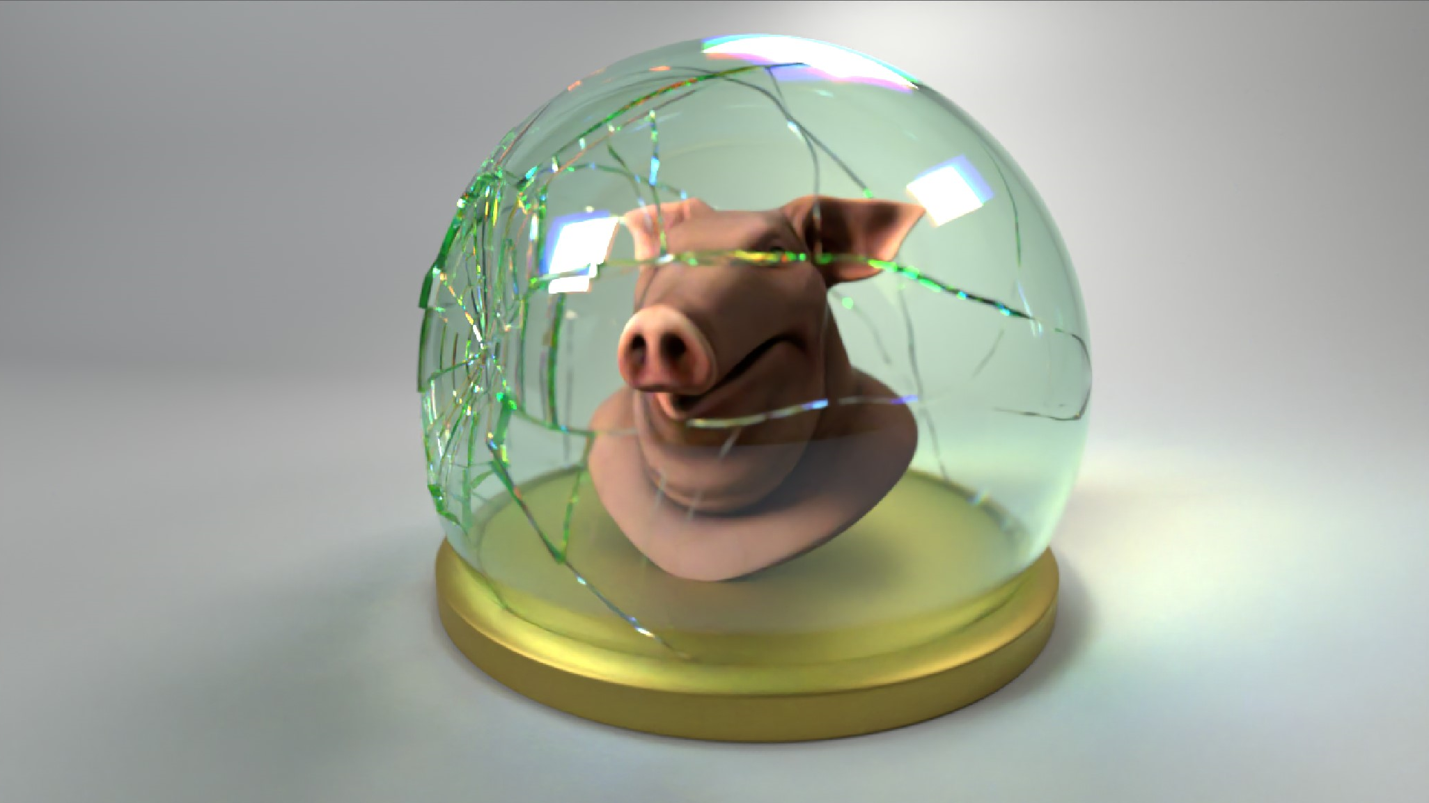
The high-level tool for pre-fracturing geometry is the ![]() RBD Material Fracture SOP, which allows you to accurately fracture geometry based on a specific type of material. The default material is concrete. You can choose Glass from the Material Type dropdown menu to change this.
RBD Material Fracture SOP, which allows you to accurately fracture geometry based on a specific type of material. The default material is concrete. You can choose Glass from the Material Type dropdown menu to change this.
Pre-fracturing 
Fracture per Piece is extremely useful when working with different panes of glass. It allows you to loop through each piece in the input geometry and fracture them individually.
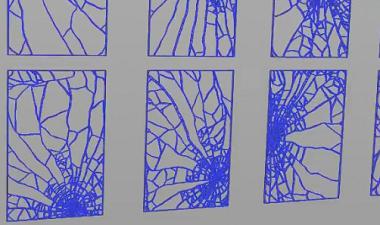
The parameters on the Cracks tab are useful for determining how many cracks you want the glass to have, as well as how they will look.
| To... | Do this |
|---|---|
|
Control how many impact points the glass has |
Increase or decrease the Scatter Points parameter. |
|
Manually determine where impact points will be |
|
|
Control how many radial cracks are created from the impact point |
Increase or decrease the Radial Crack Number parameter on the Cracks tab. If you have multiple impact points, you can use the Number Variance and Number Seed parameters to specify the variance in the number of radial cracks per impact point. |
|
Determine how many concentric cracks are created |
Decrease the Minimum Width parameter value to create more cracks, and increase the value to create less. This parameter specifies how close together the cracks are created going outward radially. Note You can also increase or decrease the Impact Spread, which specifies how far from the origin the concentric cracks can spread. |
|
Make the concentric cracks look less uniform |
Use the Discontinuity Freq and Discontinuity Size parameters to change the noise pattern. Tip You can change the change the Guide Geometry parameter to Concentric Noise to better visualize the noise pattern. The red regions show the pieces that are being kept. |
|
Get more interesting shapes in the fracture patterns |
Turn on Enable Edge Noise on the Details tab. Changing the Noise Amplitude parameter changes the whirling pattern of the noise. Altering the Noise Frequency parameter can also give you more variation in the fracture lines. |
Chipping 
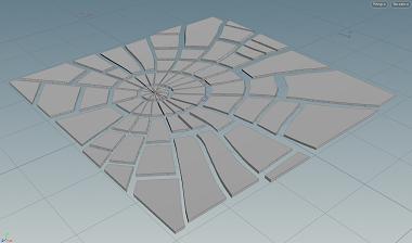
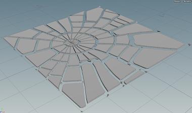
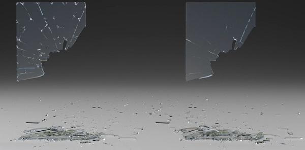
Enable Chipping on the Chipping tab will give your simulation more details, as it will chip the corners of the broken glass as it breaks apart. The image on the left shows a fractured piece of glass without any chipping, and the image on the right shows a fractured piece of glass with chipping enabled.
Understanding Chipping parameters 
The chipping parameters can give you a lot of control over the look of the chipped pieces.
| To... | Do this |
|---|---|
|
Control how many pieces get chipping applied |
Increase or decrease the Chipping Ratio parameter. A value of |
|
Determine how many of the corners get chipping applied |
Adjust the Corner Ratio. A value of |
|
Regulate how big the chips are |
Modify the Corner Depth parameter to control how big the chips will be relative to the center of the piece. Increasing this parameter will make the chips bigger. |
|
Provide variation in cutting planes |
Use the Directional Noise parameter. A value of |
|
Control how strongly the chipped pieces stick to the main fracture piece. |
Modify the Chipping Glue Strength on the Constraints tab. |
Proxy geometry 
By default, the ![]() RBD Material Fracture SOP will use the non-edge noised version (voronoi fracture shapes) as your proxy geometry. This won’t match up perfectly with the high-res geometry, but is usually close enough to give good results unless you have a very high amount of noise. Alternatively, you can turn on Use Convex Decomposition to get a closer match.
RBD Material Fracture SOP will use the non-edge noised version (voronoi fracture shapes) as your proxy geometry. This won’t match up perfectly with the high-res geometry, but is usually close enough to give good results unless you have a very high amount of noise. Alternatively, you can turn on Use Convex Decomposition to get a closer match.
Constraints 
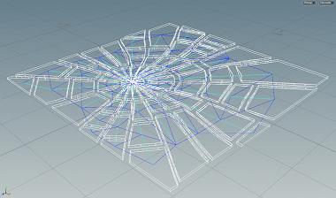
The Constraints tab has special constraints for specific groups of glass pieces, which allow you to set the strength of the glue bonds between the radial cracks, concentric cracks, and chipping. You can visualize these constraints by color if you change the Guide Geometry to Constraint Network. The constraints between radial fractures will match your Radial Color (dark blue) and the constraints between concentric fractures will match your Concentric Color (light blue).
For more information, see the Constraints help page.
Resolving issues with glass fracturing 
A common issue with glass fracturing occurs when you have interior faces with detail in pieces of glass that haven’t broken apart. This can cause problems in rendering, since it’s a transparent surface. To resolve these types of issues, you can apply a ![]() RBD Connected Faces SOP after fracturing. This node will record the primitive number and distance to the opposite face on the inside faces of the fractured geometry. You can then use this information to decide whether or not to dissolve any interior faces on pieces that haven’t broken apart by using the Delete Connected mode on the
RBD Connected Faces SOP after fracturing. This node will record the primitive number and distance to the opposite face on the inside faces of the fractured geometry. You can then use this information to decide whether or not to dissolve any interior faces on pieces that haven’t broken apart by using the Delete Connected mode on the ![]() RBD Disconnected Faces SOP.
RBD Disconnected Faces SOP.