| On this page |
Overview 
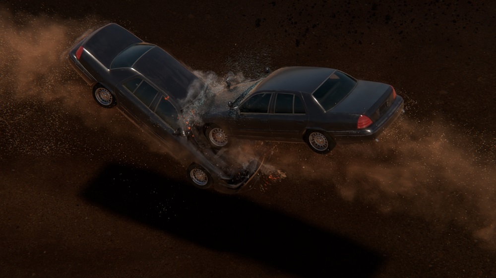
The ![]() RBD Car Fracture SOP allows you to fracture an RBD Car Rig. It provides options to fracture various materials, and creates all the constraints needed for sheet metal deformations, glass fracturing, and wood shards while allowing for some level of customization by diving inside.
RBD Car Fracture SOP allows you to fracture an RBD Car Rig. It provides options to fracture various materials, and creates all the constraints needed for sheet metal deformations, glass fracturing, and wood shards while allowing for some level of customization by diving inside.
Fitting RBD Car Fracture into your workflow 
There are two main ways of integrating the RBD Car Fracture node into your workflow.
-
Fracturing at the end of the workflow:
If you put the
 RBD Car Fracture node at the end of your workflow, it will fracture the geometry on the rest frame and then apply any input animation back onto the fractured pieces. This animation could come from an
  RBD Car Follow Path node or a Bullet simulation.
 -
Splitting out the fracturing stage:
For more efficiency, especially with heavy geometry, you can fracture the geometry separately using the
RBD Car Fracture node directly from your RBD Car Rig. You then cache the fractured geometry to disk. After that, you use an  RBD Car Transform node to transfer the animation from your RBD Car Follow Path or driving simulation onto the cached fractured geometry, and then send that into the
  RBD Bullet Solver.
Note
This method is recommended, as it helps avoid issues with upstream animation and cooking.
Car geometry 
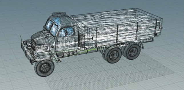
You can use your own car geometry, or you can download a truck FBX file from the Content Library. Using this with the ![]() RBD Car Rig SOP in Houdini lets you turn it into a drivable RBD vehicle. In this explanation we will be using the truck geometry, but the methods can be applied to any vehicle.
RBD Car Rig SOP in Houdini lets you turn it into a drivable RBD vehicle. In this explanation we will be using the truck geometry, but the methods can be applied to any vehicle.

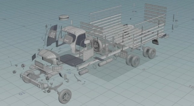
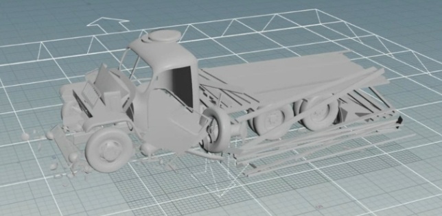
It is important to node that this model comes with a lot of disconnected pieces that need to be glued together during fracturing to prevent the car from falling apart.
Understanding RBD Car Fracture 
Setup 
-
The Chassis Group is the core structural components of the car that are not intended to be fractured. This typically includes the axles and suspension components, and it is the geometry that the wheels are constrained to.
-
The Ignore Group is anything that you don’t want to be included in the fracture at all. For example, components like antennas can sometimes be excluded from the fracture.
-
The Rest Frame is the static frame used for fracturing, which is useful when you have time-dependent animation.
-
Wheels need re-alignment when incoming geometry has animations to prevent erratic spinning.
-
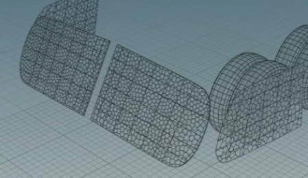
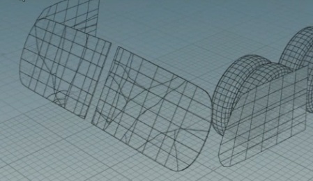
The Display options let you visualize the output geometry, proxy geometry, constraint geometry, or guides in preview mode. Guides & Preview shows fracture density without full fracturing, making it easier to adjust density interactively.
-
The Section parameter lets you choose to see the preview guide geometry for all sections or specific section names.
Materials 
There are four types of Material to choose from, which all fracture in different ways.
Glass
Safety glass creates small, uniform chunks. Impact glass creates spiderweb crack patterns.
Metal
Sheet metal is meant for thin geometry, which scatters fractures along the surface for crumpling and bending effects. It always has plastic deformations on, as it’s typically used for crumpling effects. Solid metal is for volumetric fracturing of solid chunks.
Wood
Wood material creates jagged-edged shards, similar to ![]() RBD Material Fracture wood settings.
RBD Material Fracture wood settings.
Rubber
Rubber material is similar to sheet metal but has soft, squishy constraints for tires. These constraints will will not break apart like the other materials.
Constraints 
-
Section Connector Constraints are crucial for keeping disconnected car pieces together after fracturing. If pieces fall apart when they're not supposed to, you can adjust the Search Radius. For example, if you turn off this checkbox with a model like the truck, it will fall apart without the constraints to hold it together.
-
Unique Names in Sections are important for generating constraint tags and groups, which helps with managing and breaking constraints in the
RBD Bullet Solver. You can select what’s in the Groups by preset naming of your geometry, or by selecting it interactively in the viewport. -
Glue constraints are default; however, you can control behavior by turning the Enable Plastic Deformation on or off. Turning it off will allow your material to shatter. Turning it on will switch over to bendable soft constraints upon breaking.
-
The parameters in the Constraint Attributes section are the global multipliers for the constraints. It’s recommended to change the Strength settings globally before adjusting each individual section.
-
Tweaking constraints is best done after fracturing and collision setup. That way you will already have a rough idea of what your simulation looks like. Once you're happy with this, you can make constraints stronger or weaker.
Note
The Bullet solver’s Constraint Breaking tab allows you to select constraint tags for groups, like “windows”, and set breaking thresholds.
-
Turning off Constrain to Neighbor Sections will not constrain pieces to neighboring sections. This is useful when you want to create your own constraints, such as hinges for the hood, trunk, or doors.
-
There is an optional dive target in this node for advanced users to add custom fracturing or constraints.
Fracturing 
-
Fracture Density controls the number of pieces, and Thickness adds extrusion to thin geometry for proper Bullet simulation, ensuring piece have non-zero mass and proper collisions. This can still be very thin. For example, a value of
0.005is enough to make a difference. -
Edge Detail adds noise along the cracks, giving your fracture a more interesting look. This is similar to
 RBD Material Fracture, and is very useful for simulating metal tearing.
 -
When fracturing metal, you will use these pieces to deform your high-res geometry using
 RBD Deform Pieces. It will take the bending you get from the constraints and transfer it onto your high-res geometry, so it looks like the metal is crumbling, bending, and denting.
Troubleshooting 
-
If pieces are falling off unexpectedly, you should adjust the Search Radius for the in the Section Connector Constraints section.
-
If the car stops during a simulation, particularly when using non-simulated path following, the issue is likely a lack of velocities. You can fix this either by using a
 Trail SOP to compute the velocities, or set objects to Animated initially on an
  RBD Configure SOP.
Post-processing 
-
Use
RBD Deform Pieces for metal crumpling and bending. -
Use
 RBD Car Deform for suspension and tire deformation.