| On this page |
The high-level tool for pre-fracturing geometry is the ![]() RBD Material Fracture SOP, which allows you to accurately fracture geometry based on a specific type of material. The default material is concrete. You can choose Wood from the Material Type dropdown menu to change this.
RBD Material Fracture SOP, which allows you to accurately fracture geometry based on a specific type of material. The default material is concrete. You can choose Wood from the Material Type dropdown menu to change this.
Pre-fracturing 
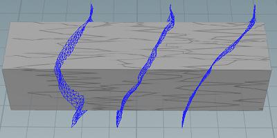
Wood uses boolean based cuts in two directions to create the grain lines and cuts. By default, the fracture direction of wood is determined by its longest point. You can see where the grain lines will be created by changing the Guide Geometry dropdown to Grains.
| To... | Do this |
|---|---|
|
Manually set the fracture direction |
Set the Fracture Direction to Vector and edit the Direction Vector parameter values. |
|
Change the number of grain lines |
Increase or decrease the Grain Spacing parameter. Decreasing the spacing will create more grain lines, and increasing the spacing will create less. |
|
Make the grain lines less uniformly spaced |
Increase the Grain Offset and Grain Offset Seed parameters. |
|
Change how jagged or smooth the grain cuts are |
Increase the Height parameter to make grains more jagged. A value of |
|
Make the grain cuts more detailed |
Decrease the Grain Detail Size parameter value to create high resolution grain cuts, and increase the value to make lower resolution cuts. |
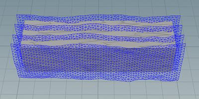
The Cut planes are created in the opposite direction of the grain lines, which you can visualize by changing the Guide Geometry dropdown to Cuts.
| To... | Do this |
|---|---|
|
Change the number of cuts |
Increase or decrease the Cut Spacing parameter. Decreasing the spacing will create more cuts, and increasing the spacing will create less. |
|
Make the cuts less uniformly spaced |
Increase the Cut Offset and Cut Offset Seed parameters. |
|
Change how jagged or smooth the cutting planes are |
Increase the Height parameter to make cuts more jagged. A value of |
|
Control the look of the splinters |
Increase the Splinter Density to create smaller splinters, or decrease it to create larger ones. You can also increase the Splinter Length to pull out some of the points in the cutting planes, which results in longer sharper cuts. Note Change the Guide Geometry dropdown to Splinters to see how the cutting planes are changed. |
Clustering 
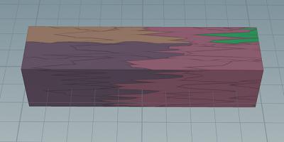
The controls on the Cluster tab are pulled from the ![]() RBD Cluster SOP for convenience. They are used to stick fractured pieces together into larger chunks that won’t break apart. This will give your simulations more variation in shapes and sizes, and looks more realistic to the way wood would naturally break apart.
RBD Cluster SOP for convenience. They are used to stick fractured pieces together into larger chunks that won’t break apart. This will give your simulations more variation in shapes and sizes, and looks more realistic to the way wood would naturally break apart.
| To... | Do this |
|---|---|
|
Visualize the clusters in the viewport |
Click the visualizer icon beside the Enable Clusters parameter. |
|
Change the size of the clusters |
Increase the Size parameter. This will create more smaller clusters instead of fewer large ones. |
For more information, see the ![]() RBD Cluster SOP.
RBD Cluster SOP.
Proxy geometry 
By default, the ![]() RBD Material Fracture SOP will use the convex hull as your proxy geometry. This won’t match up perfectly with the high-res geometry, but is usually close enough to give good results unless you have a very high amount of noise. Alternatively, you can turn on Use Convex Decomposition to get a closer match.
RBD Material Fracture SOP will use the convex hull as your proxy geometry. This won’t match up perfectly with the high-res geometry, but is usually close enough to give good results unless you have a very high amount of noise. Alternatively, you can turn on Use Convex Decomposition to get a closer match.
Constraints 
The Constraints tab has special constraints for wood pieces, which allow you to set the strength of the glue bonds between the grain lines and cutting planes. For more information, see the Constraints help page.