| On this page |
Overview 
In Houdini networks, nodes have input and output connectors, which you connect together with wires.
Wires have different meanings in different network types:
-
In Object (OBJ) networks, the connections control parenting (connect child objects to the outputs of parent objects).
-
In geometry (SOPs), compositing (COPs), dynamics (DOPs), and VOP networks connections control the flow of data through the network.
-
In render output (ROPs) networks, connections control dependencies between render passes (connect later renders to the outputs of prerequisite renders).
How to 
| To... | Do this |
|---|---|
|
Connect node inputs and outputs |
(You can click in empty space to cancel the wiring operation.) |
|
Create a new node attached to an existing input/output |
|
|
Insert a node into an existing wire |
Do one of the following to insert a node between an existing wire’s input and output.
|
|
Disconnect wires |
Do one of the following to disconnect a wire.
|
|
Branch an already-connected output to another input |
|
|
Wire nodes together by drawing across them |
|
|
Cut wires by drawing a line |
Hold Y and drag a line across a wire or multiple wires to disconnect them. |
|
Cut wires |
Hold this key and drag to cut any wires you drag over. |
Wiring tips 
-
Right-click a wire to see a menu of operations you can perform on the wire.
-
You can hold Space and pan and zoom the network view while connecting, if you need to bring the node you're connecting to into view.
-
Press Alt +
 on a node to get a menu of connectors to start wiring. This can be useful when you're zoomed out so far it’s hard to click the connectors.
 -
If you select multiple nodes and connect one of their outputs to a multi-input, Houdini automatically connects the outputs of all the selected nodes. This is useful when you want to connect a bunch of nodes to a Merge node.
-
You can hover on an input to get a tooltip explaining the purpose of the input (if the node author wrote help for the input).
Routing with dots 
The network editor lets you add “dots” to wires to route them away from a straight path between the output and input.
| To... | Do this |
|---|---|
|
Add a dot to an existing wire |
Hold Alt and click the wire. |
|
Add a dot while creating a new wire |
Click the output/input connector to start the wire, then Alt-click one or more times to add dots, then click the destination connector to finish the wire. |
|
Rewire from a dot |
Hover the mouse pointer over the dot to show input and output connectors. You can wire to/from these connectors like the usual connectors on a node. |
|
Gather multiple wires into a dot |
If you hold Alt while dragging a dot, it will “pick up” wires it crosses like walking through spiderwebs. This is a quick way of gathering a bunch of wires together. |
Pinning dots 
Dots have two states: pinned and unpinned. Alt-click a dot to toggle this state. A pinned dot has a life of its own. You can disconnect all the wires into and out of it, and it sticks around. A pinned dot is very much like a dot in Nuke, and lets you build chunks of networks, with dangling dots as scaffolding which you can connect to later.
An unpinned dot is meant to allow for simple wire routing without a lot of overhead. An unpinned dot gets automatically deleted if all the wires into or all the wires out of it get deleted (since without a wire passing all the way through it, an unpinned dot serves no purpose).
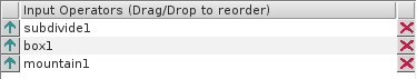
Reordering inputs 
-
Some nodes, for example the
 Merge geometry node, have “multi-inputs” that let you wire in multiple inputs.
 -
In some nodes with multi-inputs, the order of the inputs is sometimes significant. For example, Render nodes (ROPs) render their inputs in order.
| To... | Do this |
|---|---|
|
Change the order of inputs |
|
|
Quickly rotate input order |
|
| See also |