| On this page |
Absorption 
When light travels through a transparent medium such as glass, the material absorbs certain wavelengths, “coloring” the light rays. This effect is obvious when the medium is tinted, like stained glass or fruit juice.
When rendering with Mantra, this effect can be simulated in a variety of ways, such as using a volume to attenuate light as it travels through an object. However, the easiest method is to use two shader parameters on the ![]() Principled shader (as well as the
Principled shader (as well as the ![]() Classic shader and the low-level
Classic shader and the low-level ![]() PBR Nonmetallic node):
PBR Nonmetallic node):
Transmission Color
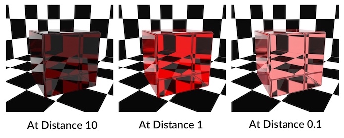
Tint rays with this color as they pass through an object. The amount of tinting depends on the distance a light ray travels within the object. You can scale the tinting using At distance.
At Distance
A ray must travel this distance within the object before it is completely colored by the Transmission color. Shorter distances give less tinting, longer distances give a darker and more saturated version of the Transmission Color.
Tip
Colors that are not fully saturated work best with the At Distance parameter.
Color components that are set to 0.0 aren’t absorbed at all, while components set to 1.0 are fully absorbed. This means that At Distance has no effect on those components.
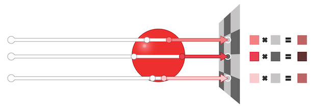
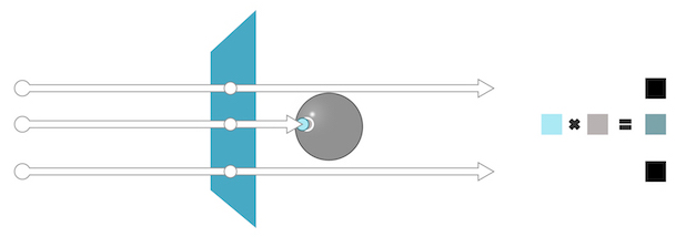
As a ray travels through a transparent object, it “accumulates” tint from the Transmission Color, according to the At Distance value. If this ray then hits an opaque object it combines the evaluated surface color with the accumulated tint.
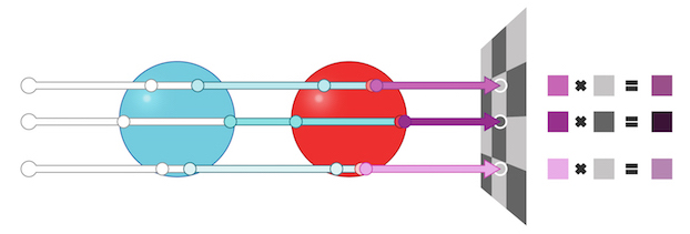
Using this method, Mantra can accumulate absorption colors across multiple, non-overlapping, transparent objects. (For a solution to overlapping transparent objects, see nested dielectrics below.) The absorption tint values are multiplied together before being combined with opaque object’s color.
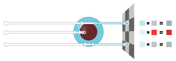
A ray does not have to exit a transparent object for absorption to take place. For example, if you have an opaque object embedded in a transparent one, the ray still accumulates absorption color before it hits the opaque surface.
The transparent object does not have to be a closed surface. A ray can pick up color from an open surface such as a plane representing a pane of glass. (Note that open transparent surfaces does not work with lights: looking at a light through a transparent plane will not color the light. If you need to tint lights, consider adding depth to your transparent object, or create emissive geometry as a stand-in for your light.)
If the tinted light ray does not eventually hit an opaque object, Mantra discards the absorption information and returns the color black, essentially treating the open surface as an infinitely Deep transparent object which absorbs all light.
“At Distance” value and scale 
When using a shader with absorption, remember than that amount of tinting is based on the distance travelled through the object in world space units. This means that the scale of your object can have a large influence on the rendered results.
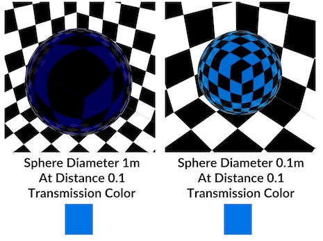
With absorption you should do your look development on an object at its actual scale in the rendered scene. If you set up the shader on an example object at one scale, but then apply it to render geometry at a different scale, you will not get the same look.
Absorption and camera position 
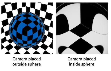
Mantra only starts tracking tint absorption when a light ray crosses a transparent surface facing the camera. This allows it to track when a ray enters an object and when it exits. However, this means placing the camera inside a transparent object will not generate the expected results. In this case, a ray leaves the camera and exits the sphere, but because it never entered the sphere from outside, it never started tracking absorption and so gets no tint from the object.
Absorption and Volumetric Effects 
Absorption is a very simple but effective way of representing the attenuation of light through a transparent medium. However, because it is not a truly volumetric effect, it is not appropriate for representing all types of lighting effects.
In some objects, the attenuation of light is caused by particulates suspended in the medium. These particles can both absorb and scatter light. Consider a large fluid effect like an ocean:
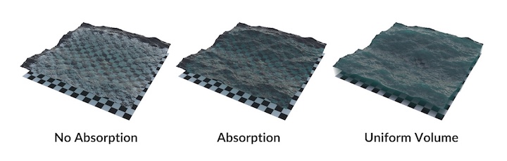
While the ocean surface has a realistic feeling of depth using absorption (center image), only the true volumetric rendering (right image) displays the characteristic light scattering of a real ocean. However, volumes are slower to render than absorbant surfaces, so you may want to consider quality vs. render time. In many cases, like a swimming pool or shallow river, absorption may be enough to get the look you need.
Nested Dielectrics 
Nested dielectrics solve a problem where you have volumes contained within other volumes that need different physical rendering properties.
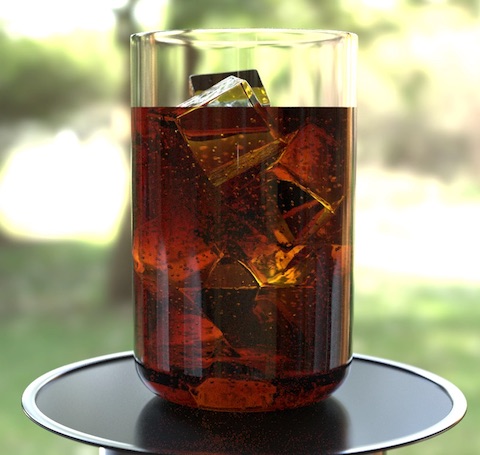
For example, for a glass of cola and ice, you want different Index of Refraction values for the glass, the cola, the ice, and the air bubbles inside.
Also, in this example, the fact that the cola geometry intersects the glass will obviously give incorrect results. You don’t want the cola to shade inside the glass interior.

You could try modeling the surfaces in such a way that the volumes of the different geometries don’t overlap – instead their surfaces would be coincident, or have a tiny gap.
However, shading coincident surfaces will always shade incorrectly due to precision errors, and a gap will not give physically correct results. Further, this is a tedious and error-prone way to model. It would be much easier to just overlap the surfaces.

The solution is nested dielectrics. You set up priorities on the different shaders, and at render time, wherever multiple shaded surfaces overlap, only the shader(s) with the highest priority contribute.
Nested dielectrics act like a cheap boolean operation at render time. Higher priority shaders run instead of lower priority shaders, effectively “scooping out” the geometry’s volume where they overlap.
In this case you would give the bubbles and glass higher priority than the cola. This lets you “scoop out” the glass and bubbles from the cola. You would give the ice higher priority than the bubbles. This lets you scatter bubbles throughout the cola and then override them with the ice wherever they overlap. Again, this means you don’t have to worry about preventing bubbles from scattering where ice exists.
| To... | Do this |
|---|---|
|
Enable nested dielectrics on the render node |
Nested dielectric support has a slight performance and memory cost. You might not want to turn it on until you need it. |
|
Set up nested dielectric shaders |
The lower the priority number, the higher the priority. For example, a shader with priority 1 will override a shader with priority 2. |
Surface Priority 
The shaded surface’s place in an order of precedence for overlapping transparent materials. A value of 0 means the surface priority should be ignored. Surfaces with lower numbers (higher priority) “override” surfaces with higher numbers (lower priority). Mantra will only calculate the shaders for the highest priority object in a given area, creating the effect of higher priority objects overriding and removing lower priority objects in the same overlapping space.
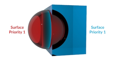
In this render, the red sphere and the blue box have the same surface priority. This causes problems with refraction and absorption, because it’s not clear to Mantra which surface is inside or outside.
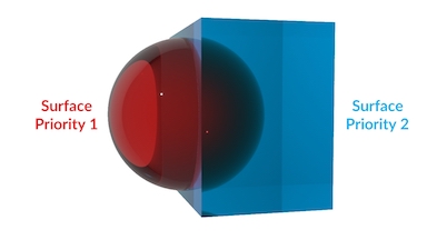
In this example, the red sphere has a higher priority than the blue box (lower numbers mena higher priority) so it “carves out” its volume from the box (Mantra simply ignores whichever parts of the box have overlapped the sphere). The absorption and refraction is now correct for the red sphere being embedded in the blue box. This setup would work well for something like ice cubes floating in water.
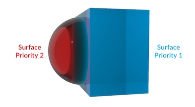
In this example, the surface priority values are switched so the blue box has higher priority. This has the effect of removing any parts of the red sphere which overlapped the blue box. This setup would work for something like water droplets resting on the surface of a glass.
This parameter only takes effect when Enable Absorption and Nested Dielectrics is turned on in the ![]() Mantra render node.
Mantra render node.
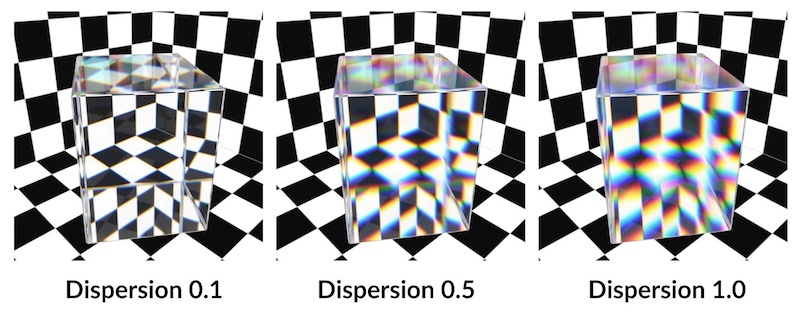
Dispersion 
In optics, dispersion can refer to the separation of light into its component wavelengths as it travels through a refractive material. A classic example of this effect is the spectrum produced by light travelling through a dispersive prism.
When rendering with Mantra, you can simulate this effect by increasing the Dispersion parameter on the ![]() Principled shader (as well as the
Principled shader (as well as the ![]() Classic shader and the low-level
Classic shader and the low-level ![]() PBR Nonmetallic node).
PBR Nonmetallic node).
Dispersion
Spreads and colors refraction rays to simulate the effect of a spectrum of wavelengths within the refracted light. The larger this value, the larger the spectral separation.
When this parameter is set to a non-zero value, refracted rays are tagged with a single wavelength in the visible spectrum. Each of these wavelengths modify the underlying index of refraction (IOR) causing the rays to separate as they travel through the refractive material.
Mantra randomly assigns the wavelengths. However, it tries to make sure that the visible spectrum is uniformly sampled per Pixel Sample.
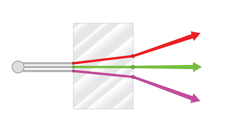
Because Mantra tags each ray with a single wavelength, it is important to have enough samples to represent the entire spectrum (using the Secondary rays parameter on the Mantra render node).
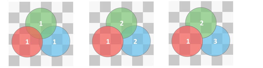
In the following diagram, you can see how a single Pixel sample, with 3 secondary rays, will not be able to adequately cover the visible spectrum. This will almost certainly result in noise in the final render as each pixel sample returns a random distribution of wavelengths.
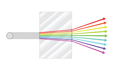
As you increase the number of secondary rays, there is more resolution to represent more of the visible spectrum in a single Pixel Sample. This will result in more consistency pixel to pixel and so less noise in the render.
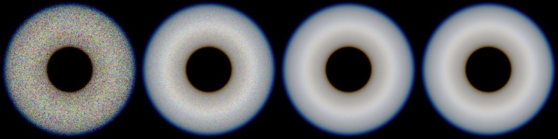
The following sequence of renders shows how noise from Dispersion decreases with the number of secondary rays. The renders show 1, 5, 25, and 100 secondary rays.
Removing dispersion noise 
Most often, noise in a render is the result of small changes in brightness (luminance) from one pixel to another. When your shader has dispersion, this grainy look can be amplified by the introduction of color noise alongside on top of luminance noise.
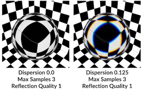
In this example, both are similarly under-sampled but the image on the right appears to exhibit much more noise. This is because small changes in brightness are far less obvious than dramatic change in color caused by insufficiently sampling the color spectrum.
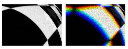
If you look closely at the white areas of the sphere, you’ll see very similar noise patterns. However, the image on the right appears dramatically noisier due to the chromatic nature of the noise.
You will often need to increase the amount of sampling on objects with dispersion compared to similar objects without dispersion.
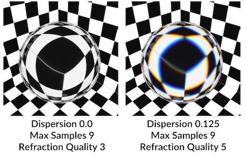
In the following example, you can see that significantly more sampling was required to achieve similar amounts of noise between both objects.

In this close-up, you can see that the white areas of the spheres now have very similar noise levels and patterns. This is because enough of the visible spectrum has been sampled to converge back to the color white. But, it required almost twice the number of samples to achieve this result.
Because of this difference in sampling, it may be useful to override Refraction Quality parameters on any transparent object with dispersion enabled. This way you can be sure that you are sending extra refraction samples only to the objects which require them.