| Since | 16.0 |
This shader aims to provide all the parameters needed to achieve a wide variety of looks.
Parameters 
Surface 
Diffuse 
General 
Enable Diffuse
Enable diffuse reflections.
Intensity
The proportion of incoming light reflected back as the diffuse
component, from 0 (no diffuse reflection) to 1 (all incoming
light is reflected). Non-attenuated lights such as point lights
and spot lights may produce brighter pixel values than this value.
(Old shaders such as the ![]() VEX Plastic shader
implicitly have a reflectivity of
VEX Plastic shader
implicitly have a reflectivity of 0.5 when the shader’s diffuse
coefficient is set to 1.)
Roughness
A floating point value used to control the size or spread of the diffuse component. Higher values make the surface look less glossy with flatter color.
Minimum
When Fresnel Blending is on, controls the minimum amount of reflection that will not be blended with the Fresnel factor. Diffuse components are blended with the transmissive Fresnel component.
Fresnel blending of the diffuse component only makes sense when one or both specular reflection layers are on. If there is no specular reflection, you should turn off Fresnel Blending.
Color 
Use Base Color
Use the base color below to color the surface. If Use point colors and/or Use color map are also on, the base color will be multiplied with them.
Base Color
The base color to use for surface shading when Use base color is on.
Use Point Color
Use values stored in the object geometry’s Cd point attributes to color the surface. If Use base color and/or Use color map are also on, the point color will be multiplied with them.
Use Packed Color
Use color attributes on packed primitives. This is multiplied against the existing diffuse color values.
Use Map
Use a texture map to color the surface. If Use base color and/or Use point colors are also on, the texture color will be multiplied with them.
Map
The texture map to use for surface shading when Use color map is on.
Tint Intensity
The blending factor between the base color and the color map, from 0 (base color only) to 1 (fully blend the color map with the base color).
Wrap
Determines what the texture looks like when the texture coordinates
are outside of the [0,1] range.
Repeat
Repeat the texture (tile).
Streak
Streak means the texture color at the edges is clamped and streaks outside the map.
Decal
Sets the color outside the texture map to the Border Color.
See ![]() texture for more information.
texture for more information.
Filter
Type of anti-aliasing filter used.
See ![]() texture for more information.
texture for more information.
Filter Width
Filter Width is the number of pixels, in both u and v directions, to use in filtering.
See ![]() texture for more information.
texture for more information.
Reflect 
Base / Coat (Same parameters) 
General 
Enable Reflection Layer
Enables this reflection layer.
Reflect Lights
Light sources (including environment lights) will be reflected. Light source reflections are commonly known as “Specular Highlights”.
Reflect Objects
This reflection layer will reflect other objects in the scene, using raytracing.
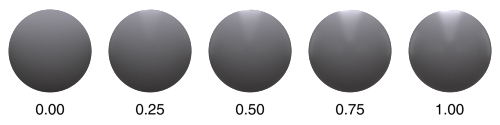
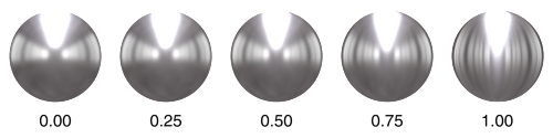
Model
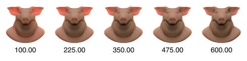
The mathematical model used to simulate glossy reflections. For each viewing angle and surface normal, the model defines from which directions and at what intensity light is reflected. This is what shapes specular highlights and reflections in general.
The overall glossiness, and with it the size of highlights, is controlled by Roughness. The available models simulate the effects caused by Roughness with varying degrees of physical accuracy, with GGX currently being the most accurate.
The chosen model has no effect when Roughness is 0, since this causes light to be reflected from a single direction at full intensity, making the model irrelevant.
See Roughness for more information.
The figure below shows the result produced by various specular models across a range of roughness values.
Note how rough surfaces look more natural with the GGX model because the interaction of light with the rough surface is modeled more accurately.

Intensity 
Intensity
The proportion of light that is reflected by this specular layer,
from 0 (no light reflected) to 1 (all light is reflected).
Note
If changing the specular color causes your diffuse color to change, it’s probably because Conserve energy is on. In that case, making the specular color unrealistically bright will require the diffuse color to become darker so the combined energy stays the same.
Use Map
Use a texture map for Intensity.
Map
The map to use when Use Map is enabled.
Channel
The channel to use from the texture map.
Wrap
Determines what the texture looks like when the texture coordinates
are outside of the [0,1] range.
Repeat
Repeat the texture (tile).
Streak
Streak means the texture color at the edges is clamped and streaks outside the map.
Decal
Sets the color outside the texture map to the Border Color.
See ![]() texture for more information.
texture for more information.
Filter
Type of anti-aliasing filter used.
See ![]() texture for more information.
texture for more information.
Filter Width
Filter Width is the number of pixels, in both u and v directions, to use in filtering.
See ![]() texture for more information.
texture for more information.
Specular Minimum
When Fresnel Blending is enabled, controls the proportion of specular reflection that will not be blended with the Fresnel factor. Increasing this parameter will cause a minimum amount of reflection to appear even for rays perpendicular to the surface.
Color 
Color
The color to tint reflections with.
Use Map
Use a texture map for the specular color.
Map
The texture map to use for the specular color when Use specular map is on.
Tint Intensity
Controls how much of an effect the map has on the end result, from 0 (specular color only) to 1 (fully blend the specular map with the specular color).
Wrap
Determines what the texture looks like when the texture coordinates
are outside of the [0,1] range.
Repeat
Repeat the texture (tile).
Streak
Streak means the texture color at the edges is clamped and streaks outside the map.
Decal
Sets the color outside the texture map to the Border Color.
See ![]() texture for more information.
texture for more information.
Filter
Type of anti-aliasing filter used.
See ![]() texture for more information.
texture for more information.
Filter Width
Filter Width is the number of pixels, in both u and v directions, to use in filtering.
See ![]() texture for more information.
texture for more information.
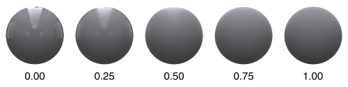
Roughness 
Amount
This is a measure of how bumpy a surface is at the microscopic level. The most obvious effect is that reflections become glossier as Roughness increases. At a value of 0, the surface is perfectly smooth and produces perfect mirror reflections. A value of 1 simulates a very rough surface, which results in very blurry reflections, similar to diffuse reflection.
In more accurate Specular Models like GGX, reflections on rough surfaces are also darkened at grazing angles. This is due to Masking-Shadowing effects, where parts of the surface are hidden from view and/or not reached by light due to microscopic grooves and spikes in the surface. Note that this is simulated using a simplified mathematical model, rather than using actual additional geometry.
The visual change when transitioning from 0 to 1 is close to linear.
Use Map
Use a texture map to control specular roughness.
Map
The texture map used to control specular roughness.
Channel
Controls which channel to use from the texture map.
Wrap
Determines what the texture looks like when the texture coordinates
are outside of the [0,1] range.
Repeat
Repeat the texture (tile).
Streak
Streak means the texture color at the edges is clamped and streaks outside the map.
Decal
Sets the color outside the texture map to the Border Color.
See ![]() texture for more information.
texture for more information.
Filter
Type of anti-aliasing filter used.
See ![]() texture for more information.
texture for more information.
Filter Width
Filter Width is the number of pixels, in both u and v directions, to use in filtering.
See ![]() texture for more information.
texture for more information.
Anisotropy 
Amount
Causes reflections to be stretched in the direction defined by Anisotropy Direction.
This simulates microscopic bumps with a directional bias, causing light to be scattered more in the defined direction. This is typical of brushed metals.
The effect of this parameter increases with Roughness. It has no effect at all when Roughness is 0.0.
Anisotropy Direction
Separate Object Reflection Parameters
Enables separate roughness, intensity, and color parameters for object reflections, independent of the parameters for specular reflections. This lets you create artistic (physically unrealistic) differences between the object reflections and light reflections.
Object Reflections 
Intensity
The intensity to use for object reflections, when Separate object reflection parameters is on. This overrides Specular Intensity.
Color
A tint color for object reflections, when Separate object reflection parameters is on. This overrides Specular Color.
Roughness
Refract 
General 
Enable Refractions
Turns on simulation of light refracting through the object.
Refract Lights
Light sources (including environment lights) will appear in refractions.
Refract Objects
Show refractions of objects. You should normally leave this option on (otherwise no refractions will appear) unless you are simulating a single sheet of reflective material, and you still want light to filter through the object.
Refraction Model
The mathematical model used to simulate glossy refractions. For each viewing angle and surface normal, the model defines from which directions and at what intensity light is refracted. This is what shapes highlights and refractions in general.
The overall glossiness, and with it the size of highlights, is controlled by Refraction Roughness.
The chosen model has no effect when Refraction Roughness is 0, since this causes light to be refracted from a single direction at full intensity, making the model irrelevant.
Thin Film Refraction
Treat the surface of the shaded object as a thin refractive film rather than the boundary between the outside of the object and a solid interior. Turn this on to simulate hollow and/or thin refractive objects such as bubbles or windows. The node still uses the refractive index to calculate the proportion of reflection and refraction for fresnel blending, but the transmitted ray will not change direction.
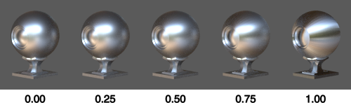
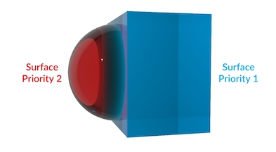
Surface Priority
The shaded surface’s place in an order of precedence for overlapping transparent materials. A value of 0 means the surface priority should be ignored. Surfaces with lower numbers (higher priority) “override” surfaces with higher numbers (lower priority). Mantra will only calculate the shaders for the highest priority object in a given area, creating the effect of higher priority objects overriding and removing lower priority objects in the same overlapping space.
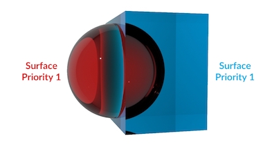
In this render, the red sphere and the blue box have the same surface priority. This causes problems with refraction and absorption, because it’s not clear to Mantra which surface is inside or outside.
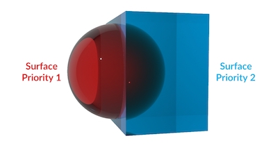
In this example, the red sphere has a higher priority than the blue box (lower numbers mena higher priority) so it “carves out” its volume from the box (Mantra simply ignores whichever parts of the box have overlapped the sphere). The absorption and refraction is now correct for the red sphere being embedded in the blue box. This setup would work well for something like ice cubes floating in water.
In this example, the surface priority values are switched so the blue box has higher priority. This has the effect of removing any parts of the red sphere which overlapped the blue box. This setup would work for something like water droplets resting on the surface of a glass.
This parameter only takes effect when Enable Absorption and Nested Dielectrics is turned on in the ![]() Mantra render node.
Mantra render node.
Intensity 
Intensity
The proportion of light refracted by the surface, from 0 (no
light refracted) to 1 (all incoming light is refracted).
Refraction Minimum
When Fresnel Blending is on, controls the proportion of refraction that will not be blended with the Fresnel factor. Increasing this parameter will cause a minimum amount of refraction to appear even for rays that graze the surface (and so would normally not refract).
Color 
Color
A tint for the refracted light (technically, the refraction amount
for different color components). For example, setting the
refraction color to 1, 0, 0 will cause the surface to refract
only red light.
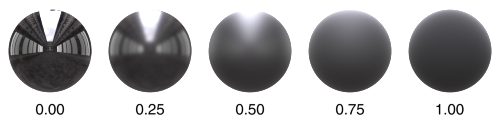
Roughness 
Amount
Roughness is a measure of how bumpy a surface is at the microscopic level. The most obvious effect is that refractions become glossier as roughness increases.
At a value of 0, the surface is perfectly smooth and produces perfect refractions like glass. A value of 1 simulates a very rough surface, which results in very blurry refractions, like milky glass.
The visual change when transitioning from 0 to 1 should be close to linear.
Anisotropy 
Amount
The direction and amount of anisotropy in the refraction. Values
less than 0 will sharpen the refraction in the U direction while
values larger than 0 will sharpen the refraction in the V
direction. When the Refraction Anisotropy is -1 or 1,
refractions will have a width of 0 in the other direction.
Transmission 
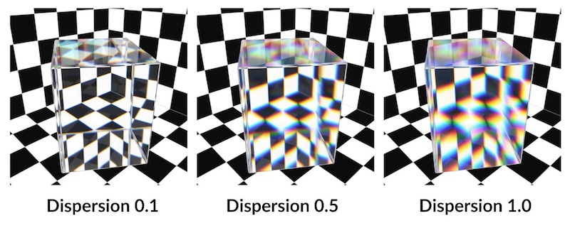
Dispersion
Spreads and colors refraction rays to simulate the effect of a spectrum of wavelengths within the refracted light. The larger this value, the larger the spectral separation.
When this parameter is set to a non-zero value, refracted rays are tagged with a single wavelength in the visible spectrum. Each of these wavelengths modify the underlying index of refraction (IOR) causing the rays to separate as they travel through the refractive material.
Transmission Color
Tint rays with this color as they pass through an object. The amount of tinting depends on the distance a light ray travels within the object. You can scale the tinting using At distance.
At Distance
A ray must travel this distance within the object before it is completely colored by the Transmission color. Shorter distances give less tinting, longer distances give a darker and more saturated version of the Transmission Color.
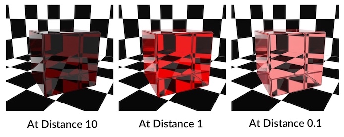
Tip
Colors that are not fully saturated work best with the At Distance parameter.
Color components that are set to 0.0 aren’t absorbed at all, while components set to 1.0 are fully absorbed. This means that At Distance has no effect on those components.
Subsurface 
General 
Enable Subsurface Scattering
Simulate subsurface scattering of light through the object.
Model
Full Subsurface Scattering
Ray traced solution based on Burley’s approximate reflectance profile.
Single Scattering
Quick approximation by only considering light that scatters exactly once inside the surface.
Random Walk (Karma)
Path traced solution that simulates light bouncing around inside the surface until it exits. Good for retaining detail and avoiding energy loss around fine edges.
Note
Not available in mantra. This feature works best with closed manifold geometry. You also need to be careful with internal geometry (e.g. eye sockets and mouth bag) since random walks will terminate when they collide with it, potentially causing unwanted darkening on the outer surface.
Amount
The overall proportion of light that is scattered, from 0 (no
scattering) to 1 (all light is scattered). Higher subsurface albedo
values will produce more multiple scattering and a greater scattering
distance.
Subsurface Minimum
The minimum scattering intensity.
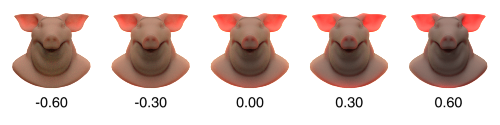
Scattering Phase
Controls the nature of the scattering. Positive values give forward scattering, 0 gives isotropic scattering, and negative values give backscattering. Range is -1 (full backscattering) to 1 (full forward scattering).
The value depends on the type of material you are trying to model. For example, skin is highly forward scattering, while marble is backscattering.
Single Scattering 
Enable Single Scattering
Enable/disable contribution from light that scatters exactly once in the surface. Certain types of surfaces (such as skin) gain little contribution from single scattering and so disabling this option will reduce computation time with little impact on accuracy.
Intensity
A scaling factor for the contribution of single scattering to the surface
color, from 0 (no contribution) to 1 (full contribution).
Quality
The number of samples for single scattering. Increase this option to decrease noise at the expense of slower shading.
Multiple Scattering 
Enable Multiple Scattering
Enable contribution from light that scatters more than once in the surface. For low albedo materials (low Subsurface Albedo), multiple scattering contributes little to the image and can be disabled to reduce computation time.
Model
Controls the way in which multiple scattering is computed. Normally you should use the Local And Global mode if you are planning to use a point cloud, and Ray Tracing to compute multiple scattering without a point cloud. Using a point cloud can produce smoother and faster results, but it requires precomputation of a point cloud and computation of irradiance for each point in the cloud (once per render).
Ray Tracing
Use ray tracing rather than a point cloud to approximate multiple scattering. This option avoids point cloud calculations but may require more sampling to eliminate noise.
Full Ray Tracing
When an single object is made of multiple packed primitives (i.e. multiple Alembic shape nodes), each shape will have local multiple scattering. With Full Ray Traced, all individual packed primitives will be considered when computing multiple scattering.
Local BRDF
Only use a BRDF function to compute the multiple scattering contribution. This is the fastest option, though no subsurface diffusion will be produced.
Global Point Cloud
Use a point cloud to compute the multiple scattering contribution. This option requires a precomputation stage to generate the point cloud and to calculate and cache the surface irradiance values in the point cloud.
Local And Global
Use the BRDF function to compute the local contribution and the point cloud to compute the global contribution, with the Local Radius Scale parameter controlling the local radius. This option will usually produce more accurate results than using a point cloud alone, especially for short scattering distances.
Path Tracing
Simulate subsurface scattering by path tracing through it as a volume. This options is slow and noisy but will produce the most accurate results - so it may be used to produce ground truth images for comparison with the other techniques.
Point Cloud Mode
Controls how the shader generates a point cloud. The simplest option is to select Generate At Render Time. This will create a new point cloud for every render. To reduce computation time, you can first use Write To File mode and then re-use the point cloud using Read From File mode on subsequent renders. This is also the recommended approach when rendering animations because the shader will smoothly interpolate the point cloud across frames. The exception to this is when the model’s topology changes (two joined polygons are separated, for example). In this case, a new point cloud must be generated. Note that in Write To File mode, the file will be overwritten if it already exists. Cancelling a render before it completes in Write To File mode may result in an unusable point cloud file.
See managing point clouds for more information.
Generate At Render Time
Always regenerate the point cloud whenever the node renders. This is convenient since you don’t have to worry about file management, and can be useful when you are modifying the shader and model at the same time. However, for efficiency you should cache the point cloud, especially when rendering animation.
Read From File
Read the point cloud from a file (specified in the Point Cloud parameter below), generated using the Write To File mode.
Write To File
Write the point cloud to the file specified in the Point Cloud parameter below.
Point Cloud File
Controls the file the point cloud is written to/read from when Point Cloud Mode is Write To File or Read From File. The point cloud is based on surface UVs, so it is not necessary to write a new point cloud file for each frame unless the topology of the model is changes.
Intensity
A scaling factor for the contribution of multiple scattering to the surface
color, from 0 (no contribution) to 1 (full contribution).
Quality
Controls the number of samples in the point cloud. Low values give fast renders but a sharper, less accurate look. High values give slower renders but a blurrier, more accurate look.
Subsurface Color 
Color
The dominant color in lit areas of the surface.
Use Map
Use a texture map to tint the rays entering the surface.
Map
The texture map to use when Use subsurface map is on.
Tint Intensity
The blending factor between the original color of the rays and the subsurface map, from 0 (original color only) to 1 (fully blend the subsurface map with the ray color).
Wrap
Determines what the texture looks like when the texture coordinates
are outside of the [0,1] range.
Repeat
Repeat the texture (tile).
Streak
Streak means the texture color at the edges is clamped and streaks outside the map.
Decal
Sets the color outside the texture map to the Border Color.
See ![]() texture for more information.
texture for more information.
Filter
Type of anti-aliasing filter used.
See ![]() texture for more information.
texture for more information.
Filter Width
Filter Width is the number of pixels, in both u and v directions, to use in filtering.
See ![]() texture for more information.
texture for more information.
Attenuation 
Density
How quickly the light intensity decreases as it scatters. Higher values make the lighting level decrease faster. Available when Parameter mode is Artist.
Color
Use Map
Use a texture map for the attenuation color.
Map
The texture map to use when Use Map is on.
Tint Intensity
The blending factor between the Attenuation color and the Attenuation map, from 0 (attenuation color only) to 1 (fully blend the attenuation map with the attenuation color).
Wrap
Determines what the texture looks like when the texture coordinates
are outside of the [0,1] range.
Repeat
Repeat the texture (tile).
Streak
Streak means the texture color at the edges is clamped and streaks outside the map.
Decal
Sets the color outside the texture map to the Border Color.
See ![]() texture for more information.
texture for more information.
Filter
Type of anti-aliasing filter used.
See ![]() texture for more information.
texture for more information.
Filter Width
Filter Width is the number of pixels, in both u and v directions, to use in filtering.
See ![]() texture for more information.
texture for more information.
Emission 
General 
Enable Emission
Add a constant amount of diffuse light emitted from the surface. For example, with emission on, the object would be visible in the render even
if none of the light objects were shining on it. This may be useful in
some circumstances, but normally you should simply use an
![]() Area Light to add light to the scene more efficiently
and controllably, especially if you need to add a lot of light.
Area Light to add light to the scene more efficiently
and controllably, especially if you need to add a lot of light.
Emission Illuminates Objects
The light emitted by this object will brighten the surfaces of other objects. When this option is off, the emitted light will be visible in the camera, but will not fall on other objects in the scene.
Intensity
The amount of emission.
Color 
Color
The color of the emitted light.
Use Map
Use a texture map for the emission color.
Map
The texture map to use when Use Map is on.
Tint Intensity
The amount of influence the map has on the final color.
Opacity 
General 
Opacity controls how transparent the object is in the scene (that is, how visible are things behind the object in the scene). Alpha controls the alpha channel of the rendered image (that is, how transparent are the pixels in the rendered image corresponding to the shaded surface).
Opacity Scale
Scales the value of the Opacity parameter. This is useful as a single number to manipulate rather than having to change all three components of the Opacity parameter together.
Color 
Color
The opacity of the red, green, and blue channels of the shaded surface color.
Use Map
Use a texture map to control the opacity of the shaded surface color.
Map
The texture to use for surface color opacity when Use Map is on.
Tint Intensity
The blending factor between the Opacity color and the Opacity map, from 0 (opacity color only) to 1 (fully blend the opacity map with the opacity color).
Wrap
Determines what the texture looks like when the texture coordinates
are outside of the [0,1] range.
Repeat
Repeat the texture (tile).
Streak
Streak means the texture color at the edges is clamped and streaks outside the map.
Decal
Sets the color outside the texture map to the Border Color.
See ![]() texture for more information.
texture for more information.
Filter
Type of anti-aliasing filter used.
See ![]() texture for more information.
texture for more information.
Filter Width
Filter Width is the number of pixels, in both u and v directions, to use in filtering.
See ![]() texture for more information.
texture for more information.
Opacity Falloff 
Enable Opacity Falloff
Blend between different opacities for parts of the surface that are perpendicular (head-on) to the camera and parts that are parallel (edge-on).
Parallel Opacity
The opacity to use for rays that are parallel to the surface normal, when Enable opacity falloff is on.
Perp Opacity
The opacity to use for rays that are perpendicular to the surface normal (rays that graze the surface), when Enable opacity falloff is on.
Opacity Rolloff
Controls the blending point between parallel and perpendicular
opacity. Values larger than 1 give more parallel opacity, values
smaller than 1 give more perpendicular opacity.
Faux Caustics 
Enable Faux Caustics
Transmissive objects produce semi-transparent shadows that attempt
to approximate the amount of light that would be transmitted if
real caustics were rendered. If you're rendering real caustics
using an ![]() Indirect Light, turn this
parameter off.
Indirect Light, turn this
parameter off.
Min Shadow Intensity
The minimum shadow intensity to use for fake caustics. Increase this to darken the lightest part of the shadow.
Max Shadow Intensity
The maximum shadow intensity to use for fake caustics. Decrease this to lighten the darkest part of the shadow.
Settings 
General 
Ensure Faces Point Forward
Automatically flip normals if necessary so planal surfaces are diffuse shaded the same way regardless of normal direction. This setting does not apply to refractions and Fresnel reflections since they rely on the normal direction to define inside and outside for Fresnel blending.
Note
If normal maps exported from another software package look strange with this option on, it may be because the normal map was output with flipped normals.
Conserve Energy
Ensures that the surface reflects no more light than it receives. This is important in physically based rendering and raytracing to ensure the illumination in the scene does not increase as the number of raytracing bounces increases. For example, a surface that reflects twice as much light as it receives (by turning off Conserve Energy and setting the Specular Intensity to 2) would produce a unnaturally bright render as you increase the Reflect Limit.
This setting conserves energy by scaling the BSDF by the inverse of its reflectivity when the node detects the reflectivity is greather than 1. This reduces all components of the surface model by the same factor, linearly darkening of the surface.
You can calculate the total reflectivity of a surface (assuming Fresnel Blending is off) by summing the Diffuse Intensity, Specular Intensity (for each layer) and Refraction Intensity. For predictable results, you should try to conserve energy manually by limiting the intensity or reflectivity parameters.
Inside IOR
The interior index of refraction for use in physical Fresnel
computations. Water has an index of refraction around 1.33.
Outside IOR
The exterior index of refraction for use in physical Fresnel
computations. Air has an index of refraction near 1.
Fresnel Blending
Turns on Fresnel blending, where the reflection and/or refraction amount varies based on the viewing angle to the surface. This allows you to simulate materials such as glass and water. You can control the proportion of Fresnel blending for each component through the “minimum” parameters on the different tabs (for example, Diffuse Minimum on the Diffuse tab).
Diffuse and Refract components use the transmissive component for Fresnel blending, while Reflect components use the reflective component.
Normal Map Export 
Source
Choose whether to output normals that have been modified by the shader, or output a difference between a high res and low res geometry.
Shader Normals
Output normals that have been modified by the shader.
Geometry Difference
Output normals in the space of the low res geometry using the high resolution geometry. Specify a low-res geometry using the UV Render Object render property on the render node. Both objects must be visible. This will lookup the normals from the high-res geometry and output them in the low-res geometry space.
Tip
When using “Geometry Different” with a high res and low res object, you should use a ![]() Peak SOP to prevent inter-penetrations artifacts in the normal map.
Peak SOP to prevent inter-penetrations artifacts in the normal map.
Space
The coordinate system in which to output the normals. Use tangent space for deforming objects, so the normals stay relative to the moving surface.
Some target applications might require a certain space for tangent maps. Commonly, game engines and other real time systems use tangent space maps.
Range
Map the normal data into specific range. Either -1 to 1 or 0 to 1.
Displacement 
General 
Map-Based Displacement
Use a texture map to displace the surface of the object at render time.
Noise-Based Displacement
Use a noise function to displace the surface of the object at render time.
The controls on this tab let you apply a displacement map and/or a bump map to the shaded surface.
Tip
You do not need to set up your own “displacement bounds” render properties when doing displacement. This material automatically sets the displacement bounds.
Displacement Scale
The scaling factor for values in the displacement textures. This depends on the scale of the scene, but will usually be very small. For example, if the scaling factor was 1.0, a value of 1 in the map would cause a displacement of 1 Houdini length unit.
Displacement Bound
The maximum bounds that the displacement shader will move geometry. This is defined in “camera” space. The absolute value is used to determine the bounds.
True Displacements
Whether to do “real” displacement (actually modify geometry at render time, allowing the silhouette of the object to change). If you turn this option off, the values of the displacement tab will be used as a bump map (creating the appearance of depth but not actually modifying the geometry or changing the object’s silhouette).
Map 
Displacement Map
The texture to use for displacing the surface.
Channel
The channel of the texture image to use as the displacement value.
If set to XYZ Displace, the RGB channels will be treated as absolute
displacements in object space. This is useful for displacing the
maps created by the ![]() Ocean Evaluate SOP. Usually a scaling factor
of 1 should be used in this case and the displacement bound set
to the maximum wave height.
Ocean Evaluate SOP. Usually a scaling factor
of 1 should be used in this case and the displacement bound set
to the maximum wave height.
Wrap
Determines what the texture looks like when the texture coordinates
are outside of the [0,1] range.
Repeat
Repeat the texture (tile).
Streak
Streak means the texture color at the edges is clamped and streaks outside the map.
Decal
Sets the color outside the texture map to the Border Color.
See ![]() texture for more information.
texture for more information.
Filter
Type of anti-aliasing filter used.
See ![]() texture for more information.
texture for more information.
Filter Width
Filter Width is the number of pixels, in both u and v directions, to use in filtering.
See ![]() texture for more information.
texture for more information.
Noise 
Noise Type
Different types of noise have different characteristics. Perlin is the standard noise. Original Perlin is similar to Perlin noise, but marginally slower to compute and with different characteristics. Sparse convolution is slower to computer and looks more random. Alligator noise is slower to computer and a very different, more cellular look from the other noise types.
Frequency
The scale of the noise pattern. Larger values give smaller, but not more detailed patterns.
Offset
Positions the noise in X, Y, and Z.
Amplitude
Scales the output of the noise function.
Roughness
Sharpens or softens the edges of the noise. Lower values are softer, higher values sharper.
Attenuation
Shifts the median value of the noise. Values greater than 1 dampen the noise down, while values less than 1 sharpen the contrast between noise values.
Turbulence
Controls the amount of detail in the noise. This is the number of times the noise function is called and summed. If the Frequency is high, there is no need for much detail, 1 or 2 should be plenty. This can affect the Amplitude of the noise as well since the summing will result in higher base values.
Bump & Normal 
Round Edge Radius
When enabled, averages normals around the specified radius (in Houdini units). This can be useful to fake beveled edges on hard surfaces.
Map Type
A normal map directly sets the surface normals. A bump map modifies the displaced normals. Set to “None” to not modify the normals.
Bump 
Use Map
Use a texture map for bump mapping.
Bump Scale
A scaling factor for the values in the bump texture.
Map
The texture to use for the bump map, when Map type is “Bump”.
Wrap
Determines what the texture looks like when the texture coordinates
are outside of the [0,1] range.
Repeat
Repeat the texture (tile).
Streak
Streak means the texture color at the edges is clamped and streaks outside the map.
Decal
Sets the color outside the texture map to the Border Color.
See ![]() texture for more information.
texture for more information.
Filter
Type of anti-aliasing filter used.
See ![]() texture for more information.
texture for more information.
Filter Width
Filter Width is the number of pixels, in both u and v directions, to use in filtering.
See ![]() texture for more information.
texture for more information.
Normal 
Use Map
Use a texture map for normal mapping.
Map
The texture map to use for normal mapping.
Wrap
Determines what the texture looks like when the texture coordinates
are outside of the [0,1] range.
Repeat
Repeat the texture (tile).
Streak
Streak means the texture color at the edges is clamped and streaks outside the map.
Decal
Sets the color outside the texture map to the Border Color.
See ![]() texture for more information.
texture for more information.
Filter
Type of anti-aliasing filter used.
See ![]() texture for more information.
texture for more information.
Filter Width
Filter Width is the number of pixels, in both u and v directions, to use in filtering.
See ![]() texture for more information.
texture for more information.
Note
The example images above use HDRIs from hdrihaven.com.
| See also |