| On this page |
Initializing a FLIP simulation with narrow band 
A standard FLIP fluid simulation begins with the liquid volume entirely filled with particles. Even with narrow band enabled in the FLIP Solver, the particles will only be removed once the simulation begins. For large simulations, these particles can occupy a large amount of memory, only to be destroyed immediately after. Instead, the FLIP simulation can be initialized directly as a narrow band.
The following example describes how to generate a fluid simulation with the narrow band initialized from the start.
-
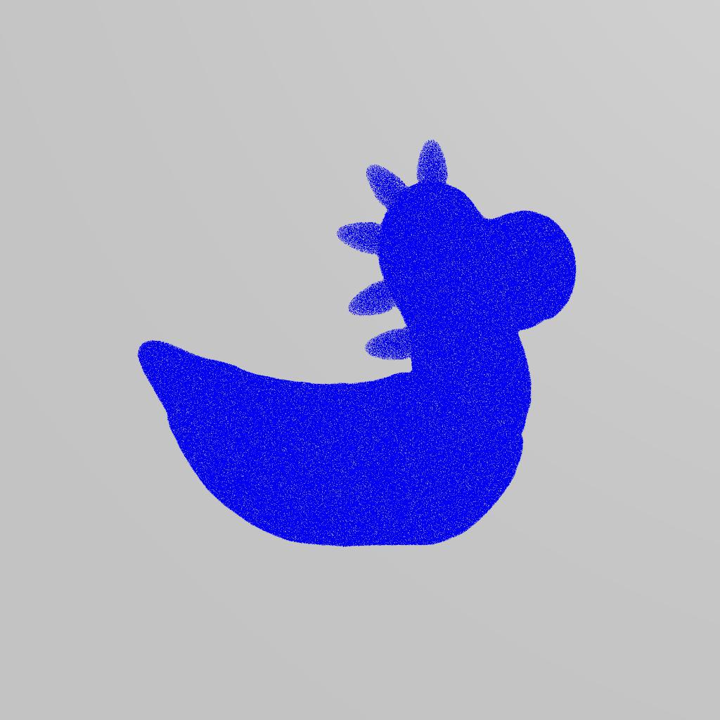
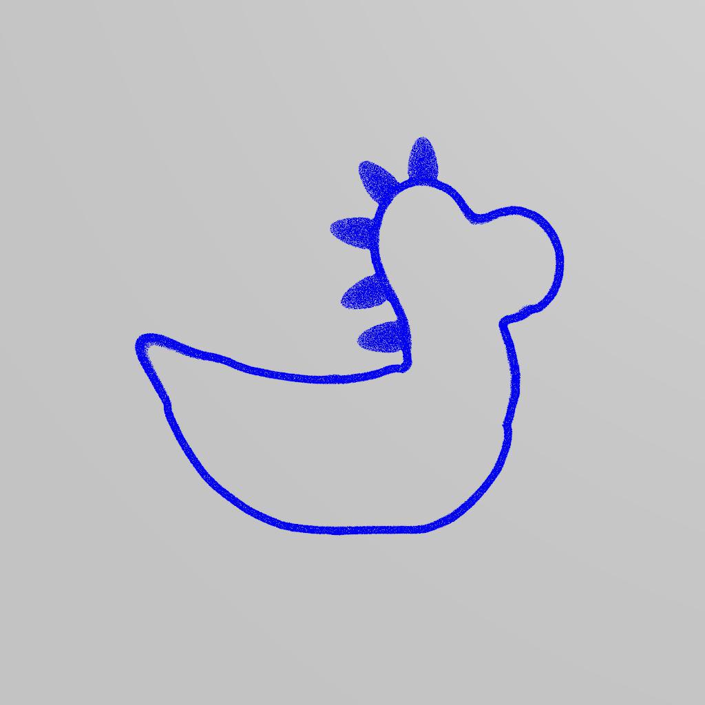
Create a
 Rubber Toy using the tab menu in the viewport. This will be the object used to create the narrow band simulation.
 -
Use the
 FLIP Fluid from Object tool on the Particle Fluids shelf to create a FLIP simulation, selecting the Rubber Toy as the object to convert to FLIP fluid.
 -
In the
testgeometry_rubbertoy_object1node, create a VDB from Polygons SOP and set the Voxel Size to match the FLIP simulation. For example, an expression that multiplies the
  FLIP Object's particle separation by its grid scale.
 -
Set the
VDB from Polygons's input to the Rubber Toy's output. -
Add a
 Null SOP node after the VDB from Polygons named SURFACE.
 -
Add a
 VDB Reshape SDF SOP after the Null, set Operation to Erode, and Offset to match the narrow band’s Bandwidth parameter in the
  FLIP Solver.
 -
Add a
VDB Combine SOP and connect the first input to the SURFACE Null's output and the second input to the VDB Reshape's output. This creates the narrow band volume to seed particles into. -
On the
VDB Combine node, set the Operation to SDF Difference. -
To seed particles in the narrow band, create a
 FLIP Source SOP and connect the input to the output of the VDB Combine node.
 -
Set the Voxel Size to match to the
VDB from Polygons node, Particle Separation to match the FLIP Object, and the oversampling settings to match the FLIP Solver. -
Add a
Null SOP node after the FLIP Source and name it PARTICLES. -
Set Input Type in the
FLIP Object to Narrow Band, the SOP Path to the PARTICLES node path, and the Surface Volume to the SURFACE node path. -
Activate Enable Particle Narrow Band in the
FLIP Solver.
Note
If you want a custom initial velocity field, it can be connected into the FLIP simulation by adding the velocity volume path to the Velocity Volume parameter in the ![]() FLIP Object DOP. The particles that have been generated above must be initialized by the same velocity field.
FLIP Object DOP. The particles that have been generated above must be initialized by the same velocity field.
Pairing particle attributes and volumetric fields 
It is not possible to set variable liquid parameters such as viscosity, density, temperature or color using particle attributes, because any particles deeper inside the liquid volume than the narrow band are removed during each simulation step. Instead, you can bind particle attribute data
to volumetric fields using the Attribute/Field Pair option.
The following example describes how to create a simulation where colored liquid pours into a clear container. The particles that sink into the container and past the narrow band are removed from the simulation, but the color persists on the volumetric field. The color attribute is advected through the simulation via this volumetric field.
-
Click the
 FLIP Tank tool on the Particle Fluids shelf to create a FLIP Tank to pour the colored liquid into.
 -
At the Object level, dive into the
fliptank_initialnode, and create an Attribute Create node between the
 initial_particlesandOUT_INITIAL_PARTICLESnodes. -
Set the Name to
Cdand Type toVector. -
In the AutoDopNetwork, add a
 Vector Field DOP between the FLIP Object and the FLIP Solver and set Data Name to
 Cd. -
Create an
 Enable Solver DOP and connect its output to the Volume Velocity (3rd) input of the FLIP Solver.
 -
Add the expression
$FF==2to the Enable Solvers parameter in theEnable Solver node in order to initialize the custom field at the beginning of the first simulated frame. This is the second frame by default. -
Create a
 Gas Match Field DOP and connect its output to the input of the Enable Solver.
 -
Set Field to
Cd, Reference Field tosurface, and Rank toVector. -
Navigate back to the Object level and click the
 Sphere tool on the Create shelf. Move it above the water level of the tank and scale to your desired size.
 -
Click the
 Emit Particle Fluid tool tool on the Particle Fluids shelf, select the sphere as the object to emit fluid from, and select the FLIP particles to emit fluid into.
 -
At the Object level, dive into the Sphere object and place an
Attribute Create SOP node between the FLIP Source node and the Null node. -
Set Name to
Cd, Type toVectorand Value to1,0,0,0. -
Navigate back to the
FLIP Solver in the AutoDopNetwork and make sure Enable Particle Narrow Band is turned on. -
Click the + button next to Attribute-Field Pairs parameter and set
Cdfor both Attribute and Field.
Note
In order to save the color fields during the simulation, add Cd to Fields in the DOP I/O node (import_fliptank) inside of the fliptank_fluid object.