| On this page |
Overview 
The Ocean shelf tab contains tools for creating ocean simulations.
The ![]()
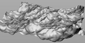
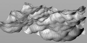
![]() Small Ocean tool is used for creating an ocean like surface. However, it is not a simulation, it is a deformer that does not use DOPs at all. You can scrub through the timeline and watch the ocean evolve without any simulation. For a simulated ocean, use the
Small Ocean tool is used for creating an ocean like surface. However, it is not a simulation, it is a deformer that does not use DOPs at all. You can scrub through the timeline and watch the ocean evolve without any simulation. For a simulated ocean, use the ![]() Wave Tank tool.
Wave Tank tool.
The ![]()
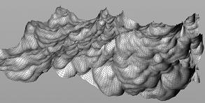
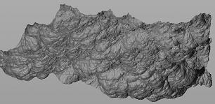
![]() Large Ocean tool is used for creating a large ocean with no repeating tiles even over very large distances. However, it is not a simulation, it is a deformer that does not use DOPs at all. You can scrub through the timeline and watch the ocean evolve without any simulation. For a simulated ocean, use the
Large Ocean tool is used for creating a large ocean with no repeating tiles even over very large distances. However, it is not a simulation, it is a deformer that does not use DOPs at all. You can scrub through the timeline and watch the ocean evolve without any simulation. For a simulated ocean, use the ![]() Wave Tank tool.
Wave Tank tool.
The ![]()
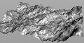
![]() Guided Ocean Layer tool creates a guided FLIP simulation of a thin particle layer on top of an ocean surface. The particles are initialized with ocean velocities. The ocean surface at a specified depth acts as a collision layer underneath the particles, allowing the particles to closely match the ocean waves. A boundary layer of particles suppresses reflections at the edge of the tank, contributes ocean velocities back to the simulation, and maintains the water volume level to match the ocean. The FLIP Simulation uses a guiding volume approach to maintain ocean velocities through the simulation.
Guided Ocean Layer tool creates a guided FLIP simulation of a thin particle layer on top of an ocean surface. The particles are initialized with ocean velocities. The ocean surface at a specified depth acts as a collision layer underneath the particles, allowing the particles to closely match the ocean waves. A boundary layer of particles suppresses reflections at the edge of the tank, contributes ocean velocities back to the simulation, and maintains the water volume level to match the ocean. The FLIP Simulation uses a guiding volume approach to maintain ocean velocities through the simulation.
The ![]()
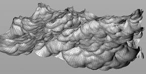
![]() Wave Tank tool creates a FLIP tank simulation with particles initialized from an ocean surface with velocities. A boundary layer of particles suppresses reflections at the edge of the tank, contributes ocean velocities back to the simulation, and maintains the water volume level to match the ocean.
Wave Tank tool creates a FLIP tank simulation with particles initialized from an ocean surface with velocities. A boundary layer of particles suppresses reflections at the edge of the tank, contributes ocean velocities back to the simulation, and maintains the water volume level to match the ocean.
The ![]()
![]() Beach Tank tool creates a FLIP tank simulation of waves breaking on a beach or other shallow water terrain. This tool is similar to the Wave Tank, except it enables an option to ramp down ocean velocities in a certain direction across the length of the tank. Reducing the velocities allow the ocean waves to break naturally as the water get shallower.
Beach Tank tool creates a FLIP tank simulation of waves breaking on a beach or other shallow water terrain. This tool is similar to the Wave Tank, except it enables an option to ramp down ocean velocities in a certain direction across the length of the tank. Reducing the velocities allow the ocean waves to break naturally as the water get shallower.
The ![]()
![]() Flat Tank tool creates a FLIP tank simulation of a flat tank of particles similar to the FLIP Tank tool, but with the addition of a boundary layer of particles that helps suppress reflections at the edge of the tank and maintain the water level over time. The boundary layer also allows the tank to track a moving object, simulating only the area around the object.
Flat Tank tool creates a FLIP tank simulation of a flat tank of particles similar to the FLIP Tank tool, but with the addition of a boundary layer of particles that helps suppress reflections at the edge of the tank and maintain the water level over time. The boundary layer also allows the tank to track a moving object, simulating only the area around the object.
Rendering ocean surfaces in Karma 
With the new Karma Ocean LOP you can render oceans inside Karma CPU. Here’s a quick guide for a basic scene.
-
From the Oceans shelf, create a Small Ocean and dive into the
ocean_geometrynode. The shelf tool automatically creates a Karma Ocean node in the stage editor. -
Save the project.
-
Click the
 ROP Geometry Output named
 save_spectra. -
Set Valid Frame Range to Render Frame Range and cache the scene with Save to Disk (in Background).
-
Repeat step 4 for the
 File Cache node named
 bake_foam. -
Connect the File Cache node’s output with the
 Merge node’s (
merge_foam) input. When you move the timeline slider, the foam should be visible. -
Switch to the stage network and click the Karma Ocean node.
-
Turn on Foam File. The appropriate path should already be available.
-
For faster iterations, set Dicing Quality to
0.25and turn off Interior Geometry. -
Add an
 Environment light node.
 -
Connect the light’s inpout with the Karma Ocean node’s output.
-
In the viewport, open the Viewport options menu and choose Karma to get a rendered preview.
Masterclass 
Differences between ocean tank types 
Tank simulation 
Creates a layer of FLIP particles on the ocean surface. The layer of FLIP particles is sitting on a collision object that is more or less the shape of the ocean. Simulation only occurs in the top layer of the ocean surface.
Fills the whole tank with FLIP Particles. Simulation occurs throughout the whole tank.
Fills the whole tank with FLIP Particles, minus the terrain object. Simulation occurs throughout the whole tank.
Fills the whole tank with FLIP Particles. Simulation occurs throughout the whole tank.
Fills the whole tank with FLIP Particles. Simulation occurs throughout the whole tank.
Waves 
Pulls in velocities from the ![]() ocean spectrum node to create a constant wave simulation.
ocean spectrum node to create a constant wave simulation.
Only has the initial wave setup. After the initial frame, the simulation will begin to deviate from underlying ocean spectrum. However, the velocity applied at the simulation boundaries will maintain energy on the surface.
Pulls in velocities from the ![]() ocean spectrum node to create directional waves across the length of the tank.
ocean spectrum node to create directional waves across the length of the tank.
Does not start with any waves, but will react to objects that disturb it.
Does not start with any waves, but will react to objects that disturb it. The waves are added at render time.
Tracking 
Can follow moving objects.
Can follow moving objects.
Can not follow moving objects.
Can follow moving objects.
Can follow moving objects.
When it is useful 
Useful for shallow objects moving through the water, like a boat.
Useful for short ocean simulations where you don’t need to control the shape or movement of the ocean.
Useful for simulating waves breaking on a beach or other shallow water terrain.
Useful for any calm water simulations that don’t require waves, or for simulations that are going to displace a lot of water, such as a whale moving around and jumping out of the water.
Useful for simulations where the interacting objects are much bigger and/or faster than the wave motion, so the ocean displacement can be added as a post-process at render time.
Understanding the network of nodes 
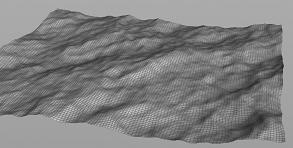
There are three important layers to focus on when creating your ocean. First create the ocean, next add whitewater, and finally add specularity for the whitewater.
Tip
Disable all whitewater nodes at the OBJ level while you work on your ocean, then disable the ocean nodes while you work on your whitewater.
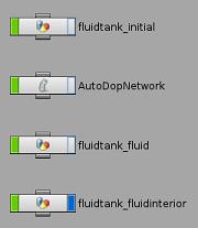
The first set of nodes control the ocean itself.
-
fluidtank_initialcontrols the first frame of your simulation. This is where you can shape the initial frame of your tank with Ocean Spectrum and control the outputs with
  Ocean Source. This includes the size of your tank, the depth of the water etc.
 -
AutoDopNetworkcontrols the simulation of your tank. This is where you will find the FLIP Object and
  FLIP Solver. The FLIP simulation will contain
  Volume Source DOPs to sink and source the boundary layer particles, and a
  Gas Guiding Volume DOP to add ocean velocities to the simulation. Note, the
  Beach Tank shelf tool uses
  POP Advect By Volumes to inject ocean velocities.
 -
fluidtank_fluidis the result of #1 and #2 combined, and is where the results are rendered. After the simulation is done, this node collects the fluid particles, sets up a material, creates some nodes for surfacing to finish the effect. -
fluidtank_interioris also used for rendering, and for creating the volumetric effect that one of the shaders applies to the interior of the fluid. It controls the volume beneath the surface, such as how cloudy or murky the water will appear.
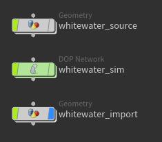
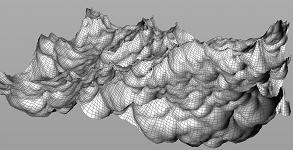
The next set of nodes are to control the whitewater.
Note
To add whitewater to your simulation, use the ![]()
![]() Whitewater tool on the Oceans shelf.
Whitewater tool on the Oceans shelf.
-
whitewater_sourceis where the spray and foam is coming from. -
whitewater_simis where the whitewater simulated. This is where you can modify the animation. -
import_whitewateris the result of #1 and #2 combined.
For more information see How to animate a wave tank with whitewater.
Note
If you build a completely procedural ocean (using the ![]() Large Ocean or
Large Ocean or ![]() Small Ocean shelf tools, for example), the
Small Ocean shelf tools, for example), the ![]() Ocean Foam SOP is used.
Ocean Foam SOP is used.
Changing the look of your ocean 
| To... | Do this |
|---|---|
|
Set the height of the wave |
Navigate to the This value is multiplied by the Speed parameter on the Wind tab.
|
|
Set the direction of the waves |
Navigate to the This controls how many frequencies are moving in the same direction as the wind. Increasing this value will cause more frequencies to travel in the same direction, which is useful for creating shoreline effects. You can also try increasing the Directional Movement parameter. This will dampen the waves moving in the opposite direction of the wind, leaving only the ones moving in the same direction.
|
|
Control the height of the peak |
Navigate to the Increasing this parameter creates sharp peaks on waves. However, if this value is too high waves, may invert on themselves.
|
|
Add more detail to your ocean |
Increase the Resolution Exponent parameter on the Note The Resolution Exponent parameter will not only determine the quality of your ocean, but also the size of the texture maps that you will eventually write out.
|
|
Create a large ocean |
Use the |
Understanding the extended ocean surface nodes 
The ![]() Guided Ocean Layer and
Guided Ocean Layer and ![]() Ocean Flat Tank tools also create a network for rendering an “extended” fluid surface that can stretch to the horizon and be rendered with ocean displacement to provide a seamless integration between a FLIP simulation and the surrounding source ocean.
Ocean Flat Tank tools also create a network for rendering an “extended” fluid surface that can stretch to the horizon and be rendered with ocean displacement to provide a seamless integration between a FLIP simulation and the surrounding source ocean.
-
The
 Particle Fluid Surface node (called
 particlefluidsurface1) creates the extended FLIP mesh. The settings on the Flattening tab of this node will flatten the fluid simulation near the edges of the simulation area, and extrude the edges of the polygonal mesh outwards to form an extended flat surface. This flat area surrounding the simulation is then rendered with ocean displacement. -
The two Particle Fluid Mask nodes (called
particlefluidmask1andhifrequency_mask) will create masks on the input ocean spectra that limit the render-time ocean displacement to specified areas of the simulation, usually where there is little velocity, vorticity, or splash height in the fluid. These nodes also blend in ocean displacement around the edges of the simulation bounding box to match the flattening applied while surfacing. Thehifrequency_masknode additionally filters the incoming ocean spectra to remove all but the highest-frequency waves, usually so these can be applied to the simulated FLIP mesh and allow it to better integrate with the surrounding ocean. -
The
surface_previewnode is a fast preview of the FLIP simulation that then samples the created mask to allow visualization of the ocean contribution using a viewport visualizer on themaskattribute. Theoceanevaluate1node applies ocean displacements to that preview based on the calculated masks. -
The
split_spectra_masksnode will separate out the static ocean spectra from the time-dependent masks created by the masking nodes. They are cached to two different sets of files to take advantage of the Ocean Surface material’s ability to have separate spectra and mask inputs.