| On this page |
Houdini’s SOP FLIP fluids provide several ready-to-use tools to illustrate some of most common workflows. To access the tools, create a ![]() Geometry SOP and double-click it to dive into the node. There, press the ⇥ Tab key to invoke the TAB menu. Enter
Geometry SOP and double-click it to dive into the node. There, press the ⇥ Tab key to invoke the TAB menu. Enter flip configure and choose ![]()
FLIP Configure Beach Tank from the list. Houdini creates a complete network and you can immediately start the simulation by clicking the ![]() icon in the playbar.
icon in the playbar.
The FLIP Configure Beach Tank tool shows how to
-
use an object as a custom container,
-
turn geometry into a FLIP fluid collision object,
-
apply custom boundary flows to a GLUP fluid simulation,
-
work with the
 FLIP Solver SOP node’s fourth input,
 -
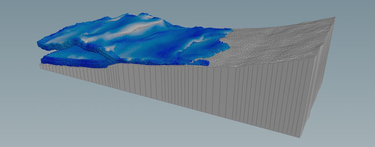
create a simulation with beach waves.
The tool creates a network for the simulation of beach waves from an ocean spectrum. The spectrum is connected to the solver’s fourth input to create a custom boundary flow. The beach collision object clips intersecting particles to create a typical shoreline with shallow and deeper zones.
Main nodes 
| Node name | Function |
|---|---|
|
|
|
|
|
|
|
|
|
|
|
|
|
|
|
|
|
|
|
|
|
Tips 
| To... | Do this |
|---|---|
|
Create more particles |
In the |
|
Use viscosity and/or surface tension |
In the |
|
Display particles instead of spheres |
Go to the |
|
Preview the waves |
|
|
Change the waves' properties |
Play with the parameters of the Wind tab, esp. Spectrum Type and Speed. Under the Amplitude tab you can eliminate smaller waves and ripples by increasing Min Wavelength. |
|
Imrpove the quality of the collision geometry |
The FLIP Collide node converts connected geometry into a volume. Quality and resolution can only be changed through the FLIP Container’s Particle Separation parameter. Doing this also affects the number fluid particles. |
|
Display particle surface with velocities |
|