Houdini’s SOP FLIP fluids provide several ready-to-use tools to illustrate some of most common workflows. To access the tools, create a  Geometry SOP node and double-click it to dive into the operator. There, press the ⇥ Tab key and enter
 flip configure. From the list choose 
FLIP Configure Wave Tank. Houdini creates a complete network and you can immediately start the simulation by clicking the  icon in the playbar.
The FLIP Configure Wave Tank tool shows how to
-
use an object as a custom container,
-
apply custom boundary flows to a FLIP fluid simulation,
-
work with the  FLIP Solver SOP node’s fourth input,
-
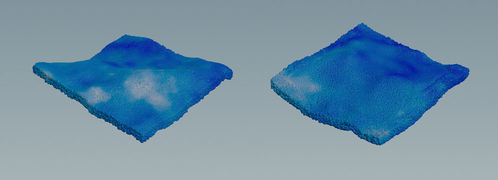
create an open ocean simulation with waves.
The tool creates a network for the simulation of an open ocean from an ocean spectrum. The spectrum is connected to the solver’s fourth input to create a custom boundary flow.
Main nodes
|
Node name
|
Function
|
|
fliptank1
|
 FLIP Container SOP. This node creates a domain where fluid simulation happens. At the domain’s boundaries, particles are sourced and deleted to maintain an equilibrium. You can connect an object to the node’s input. This object will then serve as a custom-shaped domain. The FLIP Container is also the place where you turn on physical properties like Surface Tension or Viscosity. You can also define custom attributes such as FLIP Container SOP. This node creates a domain where fluid simulation happens. At the domain’s boundaries, particles are sourced and deleted to maintain an equilibrium. You can connect an object to the node’s input. This object will then serve as a custom-shaped domain. The FLIP Container is also the place where you turn on physical properties like Surface Tension or Viscosity. You can also define custom attributes such as temperature or density. If you want to increase the number of particles, decrease Particle Separation.
|
|
oceanspectrum1
|
 Ocean Spectrum SOP. This node creates volumes containing the ocean wave information. The wave pattern is based on parameters like Direction, Speed and Scale. You can also choose from two Spectrum Type options. The default is TMA, also known as Encino waves. The Philips mode is widely known as Tessendorf waves. Ocean Spectrum SOP. This node creates volumes containing the ocean wave information. The wave pattern is based on parameters like Direction, Speed and Scale. You can also choose from two Spectrum Type options. The default is TMA, also known as Encino waves. The Philips mode is widely known as Tessendorf waves.
|
|
oceanevaluate
|
Ocean Evaluate SOP. The node used the information from the oceanspectrum1 operator to transform geometry. Under the Volumes tab you can find several expressions to drive the parameters. Velocity is mandatory, because it applies velocity to the waves and finally to the particles. The Hydrostatic Pressure option is referenced to the filpsolver1 node’s boundary Type. The Pressure mode is selected by default. Pressure tends to create a more vivid and turbulent surface. The wave setup is connected to the flipsolver1 node’s fourth input.
|
|
flipsolver1
|
FLIP Solver SOP. This node is the center piece of the network and brings everything together to simulate the fluid’s behavior. The Waterline tab is of particular interest: the Waterline checkbox has to be turned off, because the particles are created through the solver’s fourth input (Boundary Flow). Boundary Conditions are also relevant in this setup, because the fluid interacts with FLIP Container’s walls.
|
|
particlefluidsurface1
|
 Particle Fluid Surface SOP. Turn on the node’s Display/Render flag to invoke the creation of a polygon mesh, representing the fluid. Particle Fluid Surface SOP. Turn on the node’s Display/Render flag to invoke the creation of a polygon mesh, representing the fluid.
|
Tips
| To... | Do this |
|
Create more particles
|
In the fliptank1 node you can find the Particle Separation parameter. Decrease the default value to get more particles. Note that small values increase simulation time and memory usage.
|
|
Use viscosity and/or surface tension
|
In the fliptank1 node, turn on Surface Tension and Viscosity. Expand the sub-panels and enter new values for Surface Tension and Viscosity.
|
|
Display particles instead of spheres
|
Go to the flipsolver1 node’s Visualization tab and turn off Points as Spheres.
|
|
Preview the waves
|
-
Select the oceanevaluate1 node and turn on its Display/Render flag.
-
Open the Geometry tab.
-
Turn on Preview Grid.
-
Change the parameters of the oceanspectrum1 node.
|
|
Change the waves' properties
|
-
Play with the parameters of the Wind tab, esp. Spectrum Type and Speed,
-
Under the Amplitude tab you can eliminate smaller waves and ripples by increasing Min Wavelength.
|
|
Display particle surface with velocities
|
-
Select the particlefluidsurface1 node.
-
Open the Surfacing tab.
-
In the Output section, go to Visualize and choose Velocity from the menu.
|