| On this page |
Houdini’s SOP FLIP fluids provide several ready-to-use tools to illustrate some of most common workflows. To access the tools, create a ![]() Geometry SOP and double-click it to dive into the node. There, press the ⇥ Tab key to invoke the TAB menu. Enter
Geometry SOP and double-click it to dive into the node. There, press the ⇥ Tab key to invoke the TAB menu. Enter flip configure and choose ![]()
FLIP Configure FLIP! from the list. Houdini creates a complete network and you can immediately start the simulation by clicking the ![]() icon in the playbar.
icon in the playbar.
The FLIP Configure FLIP! tool shows how to
-
work with varying viscosity,
-
transfer UV texture information to a
Cdcolor point attribute, -
use the
Cdattribute to dye the fluid particles.
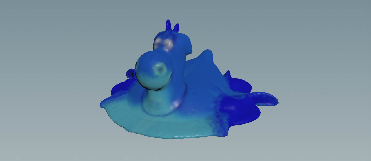
The tool creates a gradually melting ![]() Rubber Toy SOP test geometry with variable viscosity. The toy’s texture information is transferred to the particles and the particle fluid surface.
Rubber Toy SOP test geometry with variable viscosity. The toy’s texture information is transferred to the particles and the particle fluid surface.
Main nodes 
| Node name | Function |
|---|---|
testgeometry_rubbertoy
|
|
|
|
|
|
|
|
|
|
|
|
|
|
Tips 
| To... | Do this |
|---|---|
|
Change the geometry |
Create or load an object and connect it to the |
|
Change the texture |
Select the |
|
Create more particles |
In the |
|
Change the viscosity values |
Select the |
|
Display particles instead of spheres |
Go to the |
|
Show the particle fluid surface |
Turn on the |