Houdini’s SOP FLIP fluids provide several ready-to-use tools to illustrate some of most common workflows. To access the tools, create a  Geometry SOP and double-click it to dive into the node. There, press the ⇥ Tab key to invoke the TAB menu. Enter
 flip configure and choose 
FLIP Configure Ocean Layer from the list. Houdini creates a complete network and you can immediately start the simulation by clicking the  icon in the playbar.

The FLIP Configure Ocean Layer tool shows how to
-
create a guided ocean layer,
-
work with the  FLIP Solver SOP node’s fourth input,
-
customize and modify the simulation domain,
-
drive fluid particles through an ocean spectrum.
This tool creates a guided FLIP simulation of a particle layer from an ocean surface. The particles are initialized with ocean velocities. The FLIP simulation uses a guiding volume approach to maintain ocean velocities through the simulation. The network modifies the domain volume to make it a collision object for the particles. The depth of the layer will determine how closely the simulation matches the ocean surface. The depth will also determine how well the simulation can capture motion below the surface such as wakes and vortices.
Main nodes
|
Node name
|
Function
|
|
tube1
|
 Tube SOP. This node determines the shape of the simulation domain. The object is converted into a VDB volume through the Tube SOP. This node determines the shape of the simulation domain. The object is converted into a VDB volume through the vdbfrompolygons node ( VDB from Polygons SOP). VDB from Polygons SOP).
|
|
make_mask
|
 Subnetwork SOP. This node provides a custom Band parameter to adjust a mask. The mask is used to control the depth of the particle layer. Band defines the width of an area in which the mask fades out. Double-click the node to dive into the node. There you can see the network that creates the mask’s transition and the Band parameter. Below you can see the mask. Subnetwork SOP. This node provides a custom Band parameter to adjust a mask. The mask is used to control the depth of the particle layer. Band defines the width of an area in which the mask fades out. Double-click the node to dive into the node. There you can see the network that creates the mask’s transition and the Band parameter. Below you can see the mask.

|
|
adjust_domain
|
Subnetwork SOP. The domain’s volume is modified through this subnetwork to make it acts as a collision object for the particles. The node provides a custom Depth parameter to determine how closely the particles will match the ocean surface. Double-click the node to dive into it. There you can see the network that modifies the domain and defines the Depth parameter.
Note
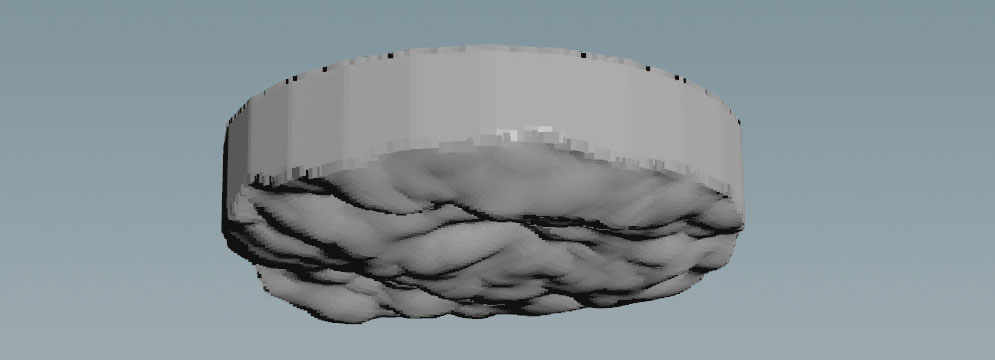
It’s not always obvious how make_mask and adjust_domain affect the simulation. To get a better impression, turn on the particlefluidsurface1 node’s Display/Render flag to invoke the creation of a mesh.
The image shows a bottom view of the clipped domain with a Depth of 0.5.
|
|
flip_tank
|
 FLIP Container SOP. This node creates a domain where fluid simulation happens. At the domain’s boundaries, particles are sourced and deleted to maintain an equilibrium. You can connect an object to the node’s input. This object will then serve as a custom-shaped domain. The FLIP Container is also the place where you turn on physical properties like Surface Tension or Viscosity. You can also define custom attributes such as FLIP Container SOP. This node creates a domain where fluid simulation happens. At the domain’s boundaries, particles are sourced and deleted to maintain an equilibrium. You can connect an object to the node’s input. This object will then serve as a custom-shaped domain. The FLIP Container is also the place where you turn on physical properties like Surface Tension or Viscosity. You can also define custom attributes such as temperature or density. If you want to increase the number of particles, decrease Particle Separation.
|
|
oceanspectrum1
|
 Ocean Spectrum SOP. This node creates volumes containing the ocean wave information. The wave pattern is based on parameters like Direction, Speed and Scale. You can also choose from two Spectrum Type options. The default is TMA, also known as Encino waves. The Philips mode is widely known as Tessendorf waves. Ocean Spectrum SOP. This node creates volumes containing the ocean wave information. The wave pattern is based on parameters like Direction, Speed and Scale. You can also choose from two Spectrum Type options. The default is TMA, also known as Encino waves. The Philips mode is widely known as Tessendorf waves.
|
|
oceanevaluate
|
Ocean Evaluate SOP. The node used the information from the oceanspectrum1 operator to transform geometry. Under the Volumes tab you can find several expressions to drive the parameters. Velocity is mandatory, because it applies velocity to the waves and finally to the particles. The Hydrostatic Pressure option is referenced to the flippsolver1 node’s boundary Type. The Pressure mode is selected by default. The wave setup is connected to the flipsolver1 node’s fourth input.
|
|
flipsolver1
|
FLIP Solver SOP. This node is the center piece of the network and brings everything together to simulate the fluid’s behavior. The Waterline tab is of particular interest: the Waterline checkbox has to be turned off, because the particles are created through the solver’s fourth input (Boundary Flow). Boundary Conditions are also relevant in this setup, because the fluid interacts with FLIP Container’s walls.
|
|
particlefluidsurface1
|
 Particle Fluid Surface SOP. Turn on the node’s Display/Render flag to invoke the creation of a polygon mesh, representing the fluid. Particle Fluid Surface SOP. Turn on the node’s Display/Render flag to invoke the creation of a polygon mesh, representing the fluid.
|
Tips
| To... | Do this |
|
Change the simulation domain’s geometry
|
Add or import an object and connect it to the vdfrompolygons1 node’s input. The tube1 node is automatically disconnected. Adjust the new domain object’s size and position with its Size and Center values.
|
|
Create more particles
|
In the fliptank1 node you can find the Particle Separation parameter. Decrease the default value to get more particles. Note that small values increase simulation time and memory usage.
|
|
Display particles instead of spheres
|
Go to the flipsolver1 node’s Visualization tab and turn off Points as Spheres.
|
|
Preview the waves
|
-
Select the oceanevaluate1 node and turn on its Display/Render flag.
-
Open the Geometry tab.
-
Turn on Preview Grid.
-
Change the parameters of the oceanspectrum1 node.
|
|
Change the waves' properties
|
Play with the parameters of the Wind tab, esp. Spectrum Type and Speed. Under the Amplitude tab you can eliminate smaller waves and ripples by increasing Min Wavelength.
|