Boulders are lose rocks of different size and the result of erosion processes, but also cataclysmic events like earthquakes. Boulders can be rough and edgy, or have a smooth surface if they've been transported by water or ice. You can, for example, find boulders in riverbeds, terminal moraines of glaciers, at the foot of a mountain, but also in sediments like sand. A boulder is at least around 25 cm (10 in) in diameter. Boulders are found in any part of the world and some even have names like the Bowder Stone in England or the Damenstenen in Denmark.
Since boulders are a common geological structure, they play an important role in the believability of synthetic terrains.
Boulder creation 
Please note that there’s no HeightField Boulder COP and the creation of boulders is a manual process. Everything starts with a terrain, for example from the  HeightField Noise COP. Then you create a certain cell pattern and manipulate it to create the impression of rocks of different size.
Cell Pattern 
The  Cell Pattern COP is one way to create boulders with different sizes and shapes. Lay down the node and turn on its blue Display flag. What you see is a mosaic-like pattern with bold black seams. In relation to the terrain, the individual tiles are way too big. On the node’s Pattern section, decrease Element Size to something around
 0.02.
You can control the shape of the tiles with Jitter and Lattice Type. The first parameter is the degree of deformation. With 0, you get a completely regular structure with squared tiles. You can proceed with the default of 0.5 or increase the value for more randomness. Lattice Type, on the other hand, defines the fundamental shape. The Grid option is responsible for the squared tiles, while Hexagonal creates a honeycomb structure. Choose Hexagonal for even more jagged tiles.
Smaller Density values remove tiles on a random basis and create clusters. With Seed you can change the distribution of the tiles.

Fractal Sample 
Right now the overall impression of the pattern is very regular. The tiles have different shapes, but they all have more or less the same size. To create tiles of different size and orientation, lay down a  Fractal Sample COP. This node takes the input image and scatters copies of different size and orientation over the plane.
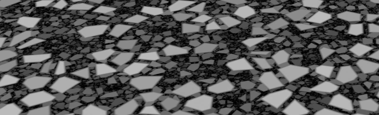
Connect the sample node’s source input with the noise output of the pattern node. When you turn on the Display flag, you can see smaller tiles that fill the gaps. To fix the overlap, open the sample node’s Blend Mode and choose Maximum. Now, the tiles are clearly separated.
Masking 
What you have now is the base structure that covers the entire terrain. However, in many cases you want the boulders to live only in specific areas. That’s a task for a mask.
Of course, you can create any kind of mask. Here you're going to use a  HeightField Mask by Feature COP. Add the mask node and connect its
 height input with the output of the last node in your terrain network, for example a HeightField Noise COP.
Before you start to adjust the noise, lay down a  Multiply COP. Connect its
 bg input with the output of the fractal sample’s fractal node. Then, link the fg input with the mask output of the mask node. Turn on the multiply operator’s Display flag. The combined view gives you a much better impression of the final result, and where the boulders appear. Now, select the mask node and make your settings. What you get could look similar to the following image.

Adding boulders 
It’s time to add the boulders to the terrain. Lay down an Add COP. Like the multiply node, add is also a preconfigured Blend COP with bg and fg inputs. The boulders should sit on top of the terrain, so they're will in the foreground. Connect the fg input with the blend output of the multiply node. Then, connect the bg input with the terrain network. In this example it’s again the noise output of the HeightField Noise COP.
When you turn the add node’s Display flag, you might be disappointed because the boulders aren’t visible. The boulder pattern is quite dark and hardly contributes to the terrain. A  Bright COP enhances the pattern and adds more height. Place the Bright COP between the multiply and add nodes to connect its
 source input and bright output. On the bright node, set Brightness to 4. You should now see displaced areas that represent the shapes of the boulders.
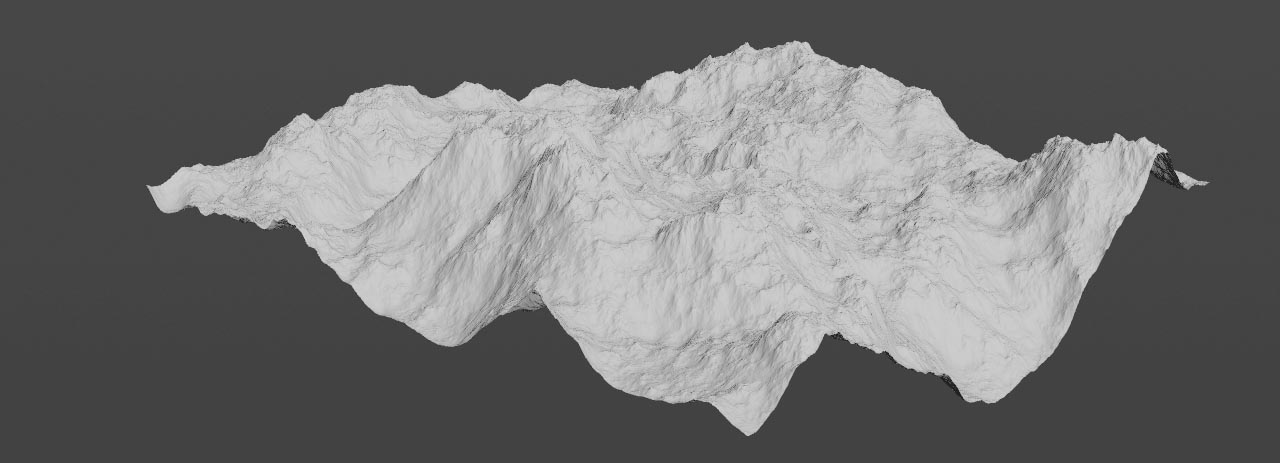
If you're not happy with the boulders, you can go back to the Cell Pattern COP and adjust the parameters of the Pattern Section, for example Element Size. The terrain in the image has a resolution of 4092 x 4092 to improve visibility.
