| On this page |
Maybe you've already visited the scripting chapter of the Masking page? There you can find a brief introduction to VEX scripting in conjunction with heightfields. The output of this guide is a circular mask. This page introduces several more example scripts that let you create various mask shapes and terrains.
To create a mask in VEX, you have to explicitly introduce the layer.
-
Lay down an empty
 Layer COP.
 -
Set the layer’s Signature to Mono.
-
Decrease Value to
0to get a completely black (= transparent) mask. -
Turn on Type Info. From the dropdown menu, choose
mask.
To execute the script, you also have perform a few steps.
-
Add a
 Wrangle COP.
 -
Set the wrangle’s Type to Mono.
-
Change Binding Name to
mask. -
Connect the
layeroutput of the layer node with themaskinput of the wrangle.
Now you can add a script. For example, copy ⌃ Ctrl + C and paste ⌃ Ctrl + V one of the scripts of this page to the node’s Snippet field.
Custom parameters 
Most scripts provide custom parameters and you can identify them by the ch() notation. In many cases, the command even defines the expected data type. For example, chf() takes floats, chi() integers, and chv() vectors. To add a custom parameter to the Wrangle COP’s UI, the script has to be present in the wrangle’s Snippet field. Then, click the  Create spare parameters for each unique call of ch() button. The parameters appear above the Snippet field.
The mask layer 
In VEX, you can address the mask layer directly like an attribute by using @mask. The @mask layer expects a float and you can directly write to variable. For example @mask = 0.5 creates a semi-transparent mask with the size of the entire terrain.
A typical question with masks is which parts should contain transparent and opaque areas? A default mask should be completely transparent and this is why you've set the layer’s Value parameter to 0. The mask script will then add non-black areas to the layer to mask out those parts where you don’t want to see any effect.
Using scripted masks 
You can connect a scripted mask to the mask input of any Copernicus node and you're not limited to terrains. A typical workflow is to use a mask in conjunction with a  Blend COP.
Scripted masks also sometimes look jagged. Add a  Blur COP after the wrangle to soften the mask’s borders.
You can also use the  Invert COP to revert the black and white tones.
Positions 
In COP-based terrains, the @P position vector attribute is connected with the Size, Center, and Uniform Scale parameters on the COP Network. This approach makes @P independent from any resolution settings.
For example with a default COP Network, if Uniform Scale is 500, the XZ dimensions range from -500 to 500 each. In this case, @P will also range from -500 to 500, and the midpoint is located at 0,0.
You can access the individual components with @P.x and @P.z. Note that the components are of type float.
Let’s take a look at a script. The example creates a white square in the upper right quadrant of the layer’s canvas.
if (@P.x > 0 && @P.z < 0) {
    @mask = 1;
}
Circle mask 
Circles are certainly one of the most often required shapes for masking. It only takes a few lines of VEX code to create such a mask.
vector position = chv("position");
vector offset = set(position.x, 0, position.z);

if (length(v@P - offset) < chf("radius")) {
    @mask = chf("mask_strength");
}
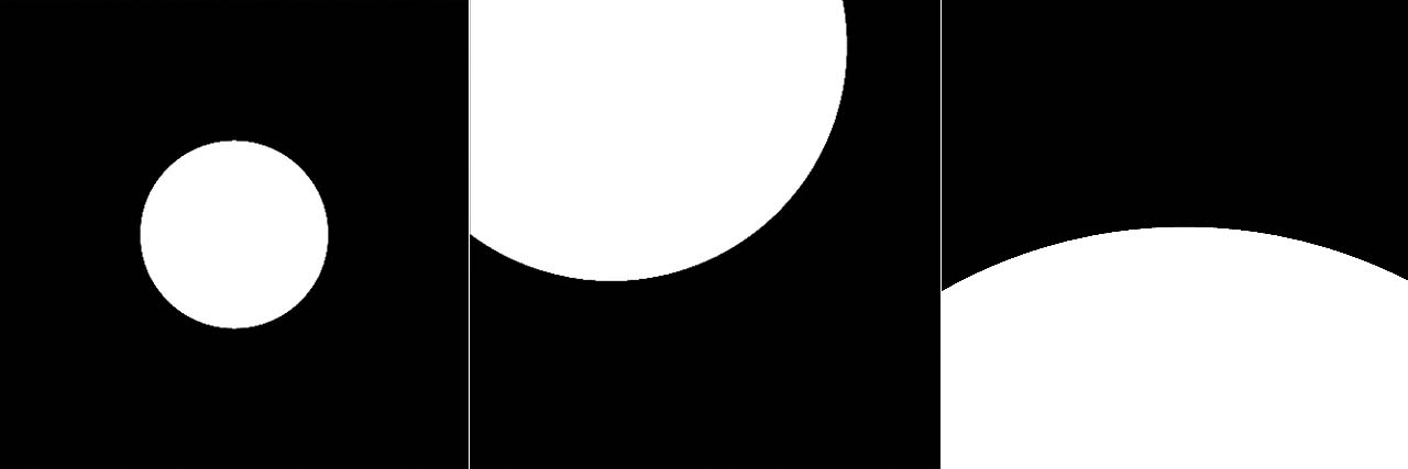
The first line reads the values from a custom position vector. This vector defines the circle’s center. The offset vector uses only the X and Z components of position because heightfields don’t have a Y value. If a heightfield element lies within the circle with a given custom radius, it’ll be added to the mask. When you set mask_strength to 1, you get a completely white circle around the defined position.
Ring mask 
Instead of a circle, you can create a ring by defining a custom inner and outer radius.
vector position = chv("position");
vector offset = set(position.x, 0, position.z);
float midpoint = length(v@P - offset);

if (midpoint > chf("inner_radius") && midpoint < chf("outer_radius")) {
    @mask = chf("mask_strength");
}
The code is very similar to the script from the Circle mask chapter. The main difference is that you compare against two values here, not just a single Radius. And length(v@P - offset) is substituted with a midpoint variable.
Oval mask 
Instead of a circle you can also create an oval mask. You need two parameters to define the oval’s X and Y dimensions. An offset defines the distance from the terrain’s default origin at [0,0] and you can rotate the shape. Also consider a Blur COP to get feathered edges.
float a = chf("x_dimension");
float b = chf("z_dimension");
vector offset = chv("offset");
float rotation = radians(chf("rotation")); // Degree -> radians
float mask_strength = chf("mask_strength"); // > 0 to see the mask

// Position of the current pixel relative to its offset
vector pos = set(@P.x - offset.x, @P.z - offset.z);

// Rotate the ellipse
vector rotated_pos;
rotated_pos.x = cos(rotation) * pos.x - sin(rotation) * pos.y;
rotated_pos.y = sin(rotation) * pos.x + cos(rotation) * pos.y;

// Test ellipse equation with transformed coordinates
float ellipse_equation = pow(rotated_pos.x / a, 2) + pow(rotated_pos.y / b, 2);

if (ellipse_equation <= 1.0) {
    @mask = mask_strength;
}
The first five lines define the parameters for customizing the ellipse. With Mask Strength you can control the mask’s opacity. The default value is 0 and you have to increase it to see a result.
The script calculates a position vector with the offset. This vector determines the oval’s center. The rotated_pos vector stores the rotated position values. The ellipse_equation defines the inner area of the ellipse. If this value is smaller than or equal to 1.0, a pixel is inside the ellipse and part of the mask.

3D Worley noise mask 
Houdini’s VEX language provides many different noise types like wnoise. You can use the various types to define masks, but also to create or manipulate terrains. The following example adds circular structures to a terrain similar to pockmarks. You’ll achieve better results when you add a Blur COP to the wrangle’s output.
For this terrain you need an empty Layer COP with Type Info set to height. The wrangle’s Binding Name must also be height.
// Parameters
vector frequency = chv("frequency");
float amplitude = chf("amplitude");
vector offset = chv("offset");
float threshold = chf("threshold");
float depth = chf("depth");
int seed;
float f1, f2, f3, f4;

// Noise values
wnoise(v@P * frequency + offset, seed, f1, f2, f3, f4);
float noise_value = f1 * amplitude;

// Create mask
if (noise_value > threshold) {
    @height = depth;
}
The terrain is quite large and most probably you need small parameter values. Start with something like:
-
Frequency =
0.005, 0, 0.005 -
Amplitude =
0.4 -
Threshold =
0.1 -
Depth =
100
The image shows the eroded result of script blended with a  HeightField Noise COP. What you get looks similar to the mountains around craters.

Ramps to heightfield 
This script converts two ramps into a heightfield. You can draw curves through the ramps and the terrain will follow their shapes. You can also define a custom Height Factor to scale the terrain. This way it’s possible to create really fancy or technically looking terrains. For this example you need an empty Layer COP with Type Info set to height. The wrangle’s Binding Name must also be height.
vector bounding_box = relbbox(0, @P);
float elevation_x = chramp("remap_x", bounding_box.x);
float elevation_z = chramp("remap_z", bounding_box.z);

float elevation = elevation_x * elevation_z;

@height += elevation * chf("height_factor");
The script creates a bounding box around the heightfield and samples the positions @P inside. The X and Z positions are then multiplied to calculate the heightfield’s elevation.
The final @height is summed up from the product of elevation and height_factor.
