| On this page | |
| Since | 16.0 |
Overview 
It can be useful to generate a texture from the rendered appearance of a model.
-
As a performance “cheat”, you can bake the fully rendered appearance of a model into a texture, and then use the texture instead of running the actual shaders. When you can get away with it (where it’s not noticeable that the object’s appearance doesn’t change), this can give a large speedup, especially for large numbers of identical objects with complex shaders.
This is especially useful when you bake a texture from a high-resolution model and apply it to a low-resolution model, possibly in combination with other resolution “tricks” such as subdivision surfaces.
-
You can capture the rendered appearance of a model as the starting point for a hand-painted texture map.
This node renders one or more objects as flat texture maps.
Note
This node is set up to make it easy to bake out known shader exports of Houdini’s Principled and Classic shaders, using the checkboxes on the Images ▸ Main tab. If you are using another shader (for example, the FBX Surface shader), you need to manually set up the exports to bake using the Extra Image Planes multiparm at the bottom of the Main tab.
UDIM and Ptex 
This node can generate UDIM unwrapped texture images, or Ptex texture maps, using the UV Unwrapping Method parameter.
-
For UDIM textures, the node will use the
uvattribute on the model to lay out the baked output.The node will replace the string
<UDIM>in the output filename with the UDIM index. -
Ptex generates a separate texture for each face and saves all the textures and the model topology together in a single archive. Since Ptex texture tiles must map to quadrilaterals, Mantra assumes the geometry will render as a subdivision surface. This node creates Ptex tiles for each polygon using the subdivision rules (3 faces for a triangle, 1 for a quad, 5 for a pentagon, 6 for a hexagon, and so on).
Baking high-res object onto low-res object 
When you specify the objects to render in the UV Render Objects, you can optionally render the appearance of one object into the UV space of another object. This is useful for baking the look of high-res geometry and complex shaders, and then applying them to a much lower-resolution object.
By default, baking will use the surface normal of the lower-resolution object for projection. This may be undesired in areas where there are normal discontinuities. For such cases, you may optionally specify UV Cage Object which is a duplicate of of UV Object whose vertices are manually pushed out slightly. The UV Cage Object will then be used to map points toward UV Object as the new projection direction.
Object pattern matching 
You can use the UV Render Objects parameter to specify multiple objects to render. You can also use wildcards in the UV Render Objects sub-parameters to match multiple objects in one go.
When you have one pattern in the UV Object path, and a corresponding * wildcard in the Output picture filename, the node will replace the * in the filename with the match from the object path.
For example, if the UV Object Path is /obj/*, and the Output Picture filename is $HIP/textures/*.rat, then the node will render /obj/apple as $HIP/textures/apple.rat, /obj/bear as $HIP/textures/bear.rat, and so on.
Note that the pattern in the UV Object path can be something other than a *. For example, if you have the objects /obj/ball1, /obj/ball2, and /obj/ball3, you could use a path of /obj/ball[1-3] and an output filename like $HIP/textures/*.rat.
Tips and notes 
-
As with a regular render, you can output multiple image planes as textures. For example shading position, direct lighting, indirect lighting, and so on.
-
Mantra unwraps the model using a lens shader (see
$HH/CVex/uvlens.vfl). Mantra only supports lens shaders in ray-tracing and PBR ray-tracing. -
The lens shader raises the “camera” very slightly above the surface, to account for precision errors in calculating the surface position. This means it’s very important to have correct surface normals on the model. If the model’s normals are reversed for some reason, you can un-reverse them on this node using the Reverse Normals parameter.
-
The uvunwrap function the lens shader uses correctly accounts for subdivided surfaces and displacement shaders when calculating the surface positions.
-
When Extract Format does not support floating point data (such as
TGA,PNGorJPG), the output values ofTangent-Space Normal (Nt)andShading Normal (N)planes will be automatically remapped from -1~1 to 0~1. -
Writing out UDIM tiles for Extra Image Planes with Different File option is currently unsupported.
Parameters 
This is a version of the regular ![]() Mantra render node which is configured with parameters to allow for easy baking of texture maps for objects. See the
Mantra render node which is configured with parameters to allow for easy baking of texture maps for objects. See the ![]() help for the render node for more general help.
help for the render node for more general help.
Texture Format
Choose “UDIM” to generate regular UV images, or “Ptex” to generate Ptex images.
Resolution
The size of the output texture image. This is ignored for Ptex textures.
Minimum Map Resolution
For Ptex, the texture size to use for the smallest faces in each object, from 4 to 1024 pixels.
Maximum Map Resolution
For Ptex, the maximum possible texture size to use, from 4 to 1024 pixels. This is a clamp on the per-face value calculated by multiplying the Minimum Map Resolution by the Map Resolution Scale.
Map Resolution Scale
For Ptex, this node calculates the size of each texture by scaling the Minimum Map Resolution based on the relative size of each face. The smallest faces will get the Minimum Map Resolution. With a scale of 1.0, faces 2× larger than the smallest will get 2× larger textures. If you set the scale to 0.0, all faces will get the minimum resolution.
UV Render Objects
For each object you want to render, click the ![]() Add button and enter the path of the object in UV Object, and the texture filename in Output Picture. You can do simple pattern expansion in the path and filename.
Add button and enter the path of the object in UV Object, and the texture filename in Output Picture. You can do simple pattern expansion in the path and filename.
-
To take the rendered appearance of a high resolution object and bake it into the texture space of the UV Object, enter the path of the High Res Object.
-
To bake using the projection direction from a cage object, enter the path of UV Cage Object.
The output picture field accepts a few special codes:
-
When Texture Unwrapping Method is “UDIM”, you can use
<UDIM>in the filename, and the node will replace it with the UDIM index to render out multiple files. -
If you enter
%(CHANNEL)sas part of the filename, the node will replace it with the channel name.
Note
Output Picture must be a floating point image format that supports multi-channel images for UDIM Post Process and Extract Image Planes to work correctly. It is strongly recommended to leave it in .rat format, and use Extract Image Planes to extract the channels into a different format.
Images 
Main 
You can use the controls on the Output tab to rename the channels in the output filenames.
Fit P To Object Bounding Box
When baking, instead of writing shading position P raw, it will be normalized to 0~1 based on bounding cube of the UV Object.
Extract image planes
When enabled, image planes contained in the output image will be extracted to separate files. The files will be saved alongside the output image, in the format: $<basename>>.‹plane_name›.‹extension›.
Remove Intermediate Output
When enabled, intermediate output file (vm_uvoutputpicture) will be deleted after the image planes have been extracted.
Shading tangent-space normal (Nt)
Displacement (Ds)
Used when baking textures. Stores the magnitude between the high-res and low-res objects.
Vector Displacement (Vd)
Used when baking textures. Stores the deltas between the high-res and low-res objects.
Tangent-Space Vector Displacement (Vdt)
Used when baking textures. Stores the deltas between the high-res and low-res objects in the low-res object’s tangent-space.
Occlusion (Oc)
Used when baking textures. The occlusion at the shading position.
Cavity (Cv)
Used when baking textures. The occlusion along the inverted normal at the shading position. This produces “relief” shading.
Thickness (Th)
Used when baking textures. The thickness at the shading position.
Curvature (Cu)
Used when baking textures. The curvature at the shading position.
Shading position (P)
Shading normal (N)
Surface Unlit Base Color (basecolor)
Surface Unlit Diffuse Color (diffcolor)
Surface Unlit Specular Color (speccolor)
Surface Emission Color (emitcolor)
Surface SSS color (ssscolor)
Surface Metallic (metallic)
Surface Roughness (specrough)
Extra image planes
These controls let you output VEX variables as auxiliary image planes, either as extra planes in the output file or extra files.
Tip
As of Houdini 9.1, each channel can now be written out to a different file. This lets you work with OpenEXR programs that don’t support multiple channels in a single .exr image.
You can also do fancy stuff like send one channel to the md device (a non-interactive MPlay window), or split your image into multiple .pic files with a handful of .tif files thrown in. But if the primary image is ip, all planes go to ip.
The Channel Name parameter lets you give the channel in the output file a different name than the default (the name of the VEX variable). For example, you want to send out the Of variable. If the Channel Name is left blank, the plane name in the .pic file will be Of. If you set Channel Name to Opacity, the plane in the .pic file will be called Opacity.
Output 
The controls on this tab let you optionally remap channel names to new strings in the output filenames. Turning on export of a channel on the Main sub-tab enables the corresponding renaming field on this sub-tab.
Name Separator
When extracting images for baking, this is the separator string that’s inserted between the filename and the channel name. For with a separator of ., the extracted image might be texture.Nt.png instead of texture_Nt.png.
Baking 
Disable Lighting/Emission
Disables all lighting on primary image plane in order to make baking faster.
Add Baking Exports to Shader Layers
Add baking related shader exports to layers structs, so they can be mixed by layer compositing operations and finally exported.
Baking samples
Number of samples to use for raytraced shading (eg. Occlusion, Cavity, Thickness). Increasing the number of samples will reduce noise in the shading.
Use MikkT Tangent Space
Use Mikkelsen’s Tangent Space for baking tangent space normals (Nt). The basis is computed per-fragment (Unreal Engine compatible). Use a ![]() Divide SOP to convert the UV Object into triangle mesh before baking because other applications may interpolate tangents across quads differently.
Divide SOP to convert the UV Object into triangle mesh before baking because other applications may interpolate tangents across quads differently.
Tangent Normal Face Forward
When enabled, backfacing normals in tangent space (i.e. its Z axis in tangent basis is negative) will be flipped to always face forward.
Tangent Normal Flip X
Toggles flipping of the normal’s X axis. Various packages may expect normal maps in different spaces. The flip parameters allow you to match these various spaces.
Tangent Normal Flip Y
Toggles flipping of the normal’s Y axis. Various packages may expect normal maps in different spaces. The flip parameters allow you to match these various spaces.
Include Displacement in Tangent Normal
Occlusion Bias
This acts as a contrast control over the occlusion shading, with values higher and lower than 0.5 resulting in more and less contrast.
Cavity Distance
Controls the distance within which features will influence the shading.
Cavity Bias
This acts as a contrast control over the cavity occlusion shading, with values higher and lower than 0.5 resulting in more and less contrast.
Occlusion-based Curvature
This is a course but fast approximation for measuring curvature. When off (the default), the renderer measures curvature using local topology. Turning this on measures curvature by casting occlusion rays. The number of occlusion rays is controlled by Baking Samples parameter.
Curvature Ray Distance
Maximum occlusion ray distance to use when Occlusion-based Curvature is on.
Curvature Scale
Multiplies the output curvature value. If you are seeing any curvature shading you should increase this value until the gradient is visible.
Curvature Bias
This acts as a contrast control over the curvature’s shading, with values higher and lower than 0.5 resulting in more and less contrast.
Custom UDIM Range
Used to specify UDIM tiles to bake. Example: “1001-1004,1011” (without quotes). If left blank, mantra will bake all UDIM tiles the UV object occupies.
Unwrapping 
Unwrap Method
Selects the method used to unwrap from the 'UV Object'.
UV To Surface
Maps the UVs to their locations on the surface of the object.
Trace Closest Surface
Uses raytracing to find the surface closest to the UV Object.
Ray Bias
Determines how much to offset the position of the ray from the surface of the object along the normal vector. This value should be increased proportional to the displacement in a displacement shader (if there is one) in order to ensure that the ray hits the surface. The bias is used solely for camera rays.
Ray Max Distance
If vm_uv_unwrap_method is set to Trace Closest Surface this parameter controls the maximum distance to trace for nearby surfaces. Useful for limiting the areas of the scene that will be baked onto the low-res object.
Reverse Normals
When texture baking, this will reverse normals on the geometry. This determines the orientation of the surface for the baking lens shader (i.e. shade the inside or outside of the surface).
UDIM Post Process
When baking to a UDIM image, this option determines what type of post-processing is applied to the final image. The choices are No Post Processing, Border Expansion, Fill Background With Average Color, and Diffuse Fill.
Note
Currently, this is only supported when rendering to disk (not to flipbooks)
UV Additional Pixels at Border
When baking to a UDIM image and performing island border expansion, this parameter indicates by how many pixels each island should be enlarged.
Orient Ptex Subfaces Clockwise
When baking to a Ptex image, this option determines the orientation of face ids for subfaces when splitting non-quad faces. The default is to order the sub-faces counterclockwise. However, some software expects to have the faces ordered clockwise.
Exclude Light Paths
This parameter controls the light components excluded during bake renders. When baking it is common to render only view-independent components such as “diffuse”. The default value of -diffuse & -volume will only render diffuse and volume light paths.
Ptex Scale Prim Attribute
When baking to a Ptex image, mantra will look for primitive-level scalar attribute of this name to scale tile resolution of current face. Note that the scaled resolution is still clamped by Minimum and Maximum resolutions.
Ptex Use Relative Scale
If this is disabled, mantra will no longer measure relative size of faces compared with smallest faces in the model when baking to a Ptex image. The tile resolution of each face will simply be Minimum Ptex Map Resolution multiplied by Ptex Resolution Scale and primitive-level Ptex scale attribute (if one exists).
Rendering 
Sampling 
Pixel samples
Controls the number of primary rays Mantra will use to sample your scene per pixel. The two numbers represent an arrangement of samples in the X and Y axis and are generally the same number. However, for non-square pixels it may be necessary to use different values in X and Y. Multiplying these two values together will give you the number of primary rays per pixel.
Increasing Pixel Samples will result in a cleaner, higher quality image. However, since all other sampling values are multiplied by the number of Pixel Samples, they should only be increased when necessary. For more details on when to increase Pixel Samples, see the “Removing Noise” section.
Ray variance anti-aliasing
When enabled, this parameter will cause Mantra to use ray variance antialiasing when determining the number of Secondary Rays to send for every Primary Ray.
This means that rather than using a specific number of rays, Mantra will first send out a small number of rays and use this sample set to evaluate the Variance. Depending on the amount of variance, Mantra will continue to send more rays up to the Max Ray Samples value. Ray Variance Antialiasing is useful for optimizing your render by sending more rays only in the areas they are needed.
In cases where the minimum number of rays to remove noise is equal to the maximum number of rays, you may save a small amount of render time by disabling Ray Variance Antialiasing.
Min Ray Samples
This value is the minimum number of secondary rays to use for each BSDF type when generating an image. When Ray Variance anti-aliasing is disabled, this number represents the number of secondary rays to send regardless of the Noise Level.
Remember, this number is multiplied by the current number of Pixel Samples and the number of BSDF types on the material being evaluated.
Volume step rate
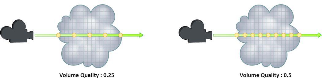
How finely or coarsely a volume is sampled as a ray travels through it. Volumetric objects are made up of 3d structures called Voxels, the value of this parameter represents the number of voxels a ray will travel through before performing another sample.
The default value is 0.25, which means that every one of every four voxels will be sampled. A value of 1 would mean that all voxels are sampled and a value of 2 would mean that all voxels are sampled twice. This means that the volume step rate value behaves in a similar way to pixel samples, acting as a multiplier on the total number of samples for volumetric objects.
For volumes that aren’t voxel based, like CVEX procedural volumes, Mantra will divide the bounding box of the volume into roughly 100 “virtual” voxels. In these cases, setting the Volume Step Rate correctly is essential to maintaining the correct level of detail.
Keep in mind that increasing the volume step rate can dramatically increase render times, so it should only be adjusted when necessary. Also, while increasing the default from 0.25 can reduce volumetric noise, increasing the value beyond 1 will rarely see similar results.
For more information about volume sampling, see sampling and noise.
Volume shadow step rate
A factor to proportionally decrease the volume step rate only for shadows, relative to the volume step rate. Smaller values will cause mantra to use a larger ray march step size for shadow rays than other shading rays. A value of 1 will produce equal quality for shadow rays and shading rays.
Stochastic transparency
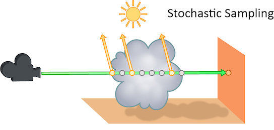
The number of transparent samples to be shaded as a ray travels through translucent objects. Increasing this value will result in less noise in translucent objects and is generally less costly than increasing Pixel samples, Volume Step Rate, or Min and Max ray samples. Stochastic Sampling will not have any effect on noise from Indirect Sources however.
This may make the image noisier than without stochastic transparency, so you may need to compensate by, for example, increasing the pixel samples. You should generally leave this option on.
The renderer ignores this option for micropolygon rendering (except for secondary ray tracing) and for renders that only generate opacity (such as deep shadow maps). In those cases it is more efficient to composite all the transparent shading results.
Added in Houdini 12.
Stochastic samples
The number of transparent samples to shade when Stochastic Transparency is on. Higher values improve shading quality for volumes and transparent surfaces, but are slower to render.
Sample lock
Sampling generally occurs in random patterns which change on every frame of an animation. This can cause a distracting “buzz” when there is a significant amount of noise in your images which can make evaluation of other aspects of the scene difficult. Enabling this parameter will “lock” the sampling patterns so that the noise remains the same on every frame.
Also, in some cases where the final rendered images will be sent through a post-render de- noise process, it can be useful to have the noise remain constant frame to frame. Consistent sampling patterns can help when analyzing the noise.
It defaults to “off” because it is generally unacceptable to have a locked sampling pattern for final sequences.
Random seed
Adjusting this parameter will cause the pixel sampling patterns used by Mantra to be regenerated in different configurations. By default, the patterns change on every frame, so manually changing this value is not necessary.
Allow image motion blur
Occasionally, when motion blur is going to be added to an image as a post-process or for other compositing operations, it is necessary to calculate the motion blur but not include it in the final rendered image. In these cases, Allow Image Motion Blur should be disabled.
This means that the blurred positions necessary for Motion Blur can be exported as a custom Motion Vector Image Plane from within a shader using the GetBlurP() function without the small overhead of doing the actual shading in the render.
This parameter is related to the motion blur parameters which are available only when Motion Blur is enabled. Disabling this option will cause motion blur to be removed from the final rendered image, however the blurred Position will still be calculated, allowing for custom motion vector image planes to be created.
Advanced 
Objects 
The parameters on this tab determine which objects and lights are included in the IFD.
Mantra processes these parameters in the following order:
-
Candidate objects/lights are selected.
-
Forced objects/lights are added.
-
Objects/Lights matching the exclusion parameter are removed.
Candidate Objects
The geometry objects in this parameter will be included in the IFD if their display flags are turned on and their display channel is enabled.
Force Objects
Objects in this parameter are added to the IFD regardless of the state of their display. Objects can only be added to the IFD once.
Forced Matte
Objects forced to be output as matte objects.
Forced Phantom
Objects forced to be output as phantom objects.
Exclude Objects
Objects in this parameter are excluded from the scene, regardless of whether they are selected in the Candidate Objects or Force Objects.
Solo Light
Only lights in this parameter will be included in the IFD. This includes shadow map generation and illumination. If this parameter is set, the candidate, forced, and exclusion parameters are ignored.
Using this parameter in conjunction with the render_viewcamera property provides a quick way of generating shadow maps for selected lights.
Candidate Lights
Each light in this parameter is added to the IFD if the dimmer channel of the light is not 0. The standard light sets the dimmer channel to 0 when the light is not enabled.
Force Lights
The lights in this parameter are added to the IFD regardless of the value in their dimmer channels.
Exclude Lights
These lights will be excluded from the scene, even if they are selected in Candidate Lights or Force Lights__.
Headlight Creation
If there are no lights in the scene, a headlight is created by default. To disable, turn off this checkbox.
Visible Fog
The fog/atmosphere objects in this parameter are included in the IFD if their display flags are turned on and their display channel is enabled.
Scripts 
Each script command refers to an hscript command which will be run, regardless of the expression language selected for the parameter. The resulting string will be run as an hscript command. It is possible to use the python, unix or source hscript commands to perform complex processing.
The commands are always run when rendering occurs. The command checks the parameters of the output driver when it is rendering a range or sending output to a command.
Before the render occurs, Houdini will automatically set the current hscript directory to point to the output driver.
Pre-Render Script
This command is run before any IFDs are generated. It is only run once per render.
Pre-Frame Script
This command is run before each IFD is generated.
Post-Frame Script
This command is run after each IFD is generated. Although the IFD may have been generated, this does not necessarily mean that mantra has finished rendering the image when this command is run.
Post-Render Script
This command is run one time, after all IFDs have been generated. Although the IFD may have been generated, this does not necessarily mean that mantra has finished rendering the image when this command is run.
Driver 
Command
The command (i.e. mantra) where the IFD file is sent. This will be disabled if the IFD file is saved to disk.
Note
The Mantra ROP will not automatically gzip based on the file extension of the .ifd file. The file .ifd.gz will contain uncompressed data. However, you can set your render command to something like gzip > foo$F4.ifd.gz to compress the file.
Disk File
The location where the IFD file is saved to disk. You must turn on the Disk File checkbox to enable this parameter.
Wait for Render to Complete
When sending the output to a command, Houdini will normally return control after it is finished writing the IFD. This allows the render process to complete in the background. Turning on this parameter will force Houdini to block until the mantra finishes rendering the frame.
When rendering a frame range, this option is automatically turned on. However, the option is not automatically turned on when rendering in an hscript or python loop construct. Therefore caution must be used or it is possible to end up starting multiple background renders.
Note
The rps and rkill hscript commands can be used to query or kill background renders.
See the Troubleshooting section for more information.
Initialize Simulation OPs
If this option is turned on, POP and DOP simulations will be initialized before rendering.
Show In Viewport
Enabling this checkbox will cause the driver to show up in the viewport menu. By default, SOHO output drivers to not appear in the viewport menu.
Save Binary Geometry
Saves binary geometry in the IFD. If this option is turned off, ASCII geometry is saved in the IFD. Binary is much more efficient. ASCII is readable.
| See also |