The transform data and most camera parameters are imported from the USD
primitive by this node. Only UsdGeomCamera standard parameters are imported
to the camera object, not any renderer-specific values.
Parameters 
Main 
LOP Path
Path to the source LOP Node.
Primitive Path
Scene graph path of the primitive whose transform will drive the transform of this camera. This parameter accepts a USD primitive pattern. If multiple primitives match the pattern, only one primitive will be used.
Transform Type
Controls what portion of the USD primitive’s transform is used to drive this object’s transform.
Local to World
Imports the full transform of the specified primitive, including both the local transform of the primitive and the transforms of all ancestor primitives.
Local
Imports just the local transform specified on the primitive itself. Transforms of ancestor primitives are ignored.
Parent to World
Ignores the local transform of the target primitive, and only imports the cumulative transform of all ancestor primitives.
Set Wireframe Color
Use the specified wireframe color
Wireframe Color
The display color of the object
Viewport Selecting Enabled
Object is capable of being picked in the viewport.
Select Script
Script to run when the object is picked in the viewport. See select scripts .
Cache Object Transform
Caches object transforms once Houdini calculates them. This is
especially useful for objects whose world space position is
expensive to calculate (such as ![]() Sticky objects),
and objects at the end of long parenting chains (such as
Sticky objects),
and objects at the end of long parenting chains (such as
![]() Bones). This option is turned on by default for Sticky and
Bone objects.
Bones). This option is turned on by default for Sticky and
Bone objects.
See the OBJ Caching section of the Houdini Preferences window for how to control the size of the object transform cache.
View 
Icon scale
Scales the viewport geometry. This parameter is only for display purposes.
Resolution
The output resolution in pixels. Standard presets are available via the pull down menu to the right of the parameter.
Pixel aspect ratio
The pixel aspect ratio of the output image.
Projection
Type of camera projection used for rendering (for example, perspective or orthographic).
Perspective
This simulates the classic pinhole camera where camera rays emanate from a common camera origin through a flat camera plane.
Orthographic
This uses parallel camera rays that are orthogonal to the (flat) camera plane. The width of the view volume is determined by the Ortho Width parameter below.
Polar (panoramic)
This projection uses a spherical camera plane for rendering.
Cylindrical (panoramic)
This projection uses a cylindrical camera plane for rendering.
Lens Shader: Use a lens shader to initialize rays for ray tracing.
Selecting Polar, Cylindrical or Lens Shader will automatically switch the Rendering Engine (on the output driver) to Ray Tracing, as it is impossible to render these projections with micropolygon rendering.
Lens Shader
Specifies the CVEX lens shader to use for the Lens Shader projection
type. A lens shader is responsible for computing primary rays from
screen coordinates, and is a flexible way to define new kinds of camera
projections that can’t be modeled as perspective or orthographic
projections. Lens shaders can have the following parameters and
exports:
float x
X screen coordinate in the range -1 to 1.
float y
Y screen coordinate in the range -1 to 1.
float Time
Sample time.
float dofx
X depth of field sample value.
float dofy
Y depth of field sample value.
float aspect
Image aspect ratio (x/y).
int xres
Image horizontal resolution.
int yres
Image vertical resolution.
export vector P
Ray origin in camera space.
export vector I
Ray direction in camera space.
export int valid
Whether the sample is valid for measuring.
The lens shader should be able to handle x and y values outside the -1 to 1 range, in case samples outside the image need to be generated. The P and I exports should be created in camera space, ignoring the camera transform.
Before rendering begins, mantra measures the lens shader before
rendering. During the measuring process, the valid variable can be used
to flag invalid rays. In the future, the valid flag may be used during
rendering.
Mantra’s camera space is defined with positive z-values in front of the camera, so for a default camera the z-axis is flipped relative to Houdini’s world space.
An example lens shader is the ![]() Ray Lens shader.
Ray Lens shader.
Focal length
Camera focal length (zoom).
Focal units
The units used for the focal length. This controls the depth of field units for mantra. The field of view is determined solely by the ratio of the focal length to the aperture. Since both are in the same units, the only change will show up in depth of field.
Aperture
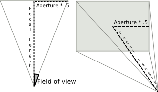
Width of the visible field.
You can obtain a good fit between the Houdini camera and a real world camera by matching a measured lens’s horizontal angle of view, and deriving a Houdini focal length value that reproduces it with the default aperture 41.4214.
Note
The default aperture combined with the default focal length of 50mm produces a 45 degree field of view.
Ortho width
Width of orthographic view volume when using Projection is set to Orthographic.
Near clipping
Position of near clipping plane.
Far clipping
Position of far clipping plane.
Background Image
Specifies a deep camera/shadow image to use to fill in the background color for primary rays (and only primary rays).
Because the deep camera/shadow image stores the color/opacity values for all depths, the deep image can be mixed with other objects in the scene with perfect occlusion/transparency.
Add this property to a camera (not the output driver). If you add it to the output driver, the background image will be picked up for shadow map generation, which is probably not what you want.
If you add this property to a light, the image will be merged with shadow maps generated shadow maps from the light.
Mantra uses OCIO to color correct images on disk. It may be able to guess the image’s color space based on the image filename (for example, myimage-srgb.exr) or format.
Screen window X/Y
Define the center of the window during the rendering process.
Screen window size
Scale for expanding the cropped area specified by the Crop parameters.
Screen window mask
Sets the screen window mask to cover the bounding box of the selected object(s).
Left crop
Left cropping margin for camera’s view area.
Right crop
Right cropping margin for camera’s view area.
Bottom crop
Bottom cropping margin for camera’s view area.
Top crop
Top cropping margin for camera’s view area.
Crop Mask
Sets the pixel crop region to cover the bounding box of the selected object(s).
Note
You can optionally add the spare parameter Visible Objects from the Parameter Interface. This allows you to control which objects are displayed in the viewport when looking through the camera.
Sampling 
Shutter time
The shutter time refers to the portion of a frame the shutter is actually open. On a physical camera, this if often referred to as Shutter Speed. The renderer uses this determine motion blur. The value should be in the range [0,1].
A value of 0 for the shutter time would mean that there is no motion blur at all, as the shutter is only “Open” for an instant. A value of 1 on the other hand would mean that the shutter is open for the entire length of the frame.
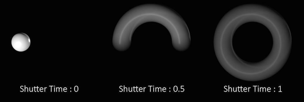
In the above example the sphere is rotating a full 360 degrees over the course of a single frame. You can see how the length of the “motion trail” or “blur” changes based on the shutter time. In most cases, the default value of .5 is appropriate for animated sequences and a good match for real world settings.
Keep in mind that this parameter controls the amount of time within a single frame, that the shutter is open. It does not refer to how long an individual frame is. To adjust the frame rate, change the Frames per Second parameter in the Global Animation Options.
Focus distance
The lens focal distance and distance from the camera at which objects will be in focus. This is only used when rendering using depth of field. Objects outside this distance will be blurred.
F-stop
Lens fstop. This is only used when rendering using depth of field. Determines blurriness of depth of field effects.
Bokeh
Filter kernel used in depth of field rendering. Use the pop-up menu to the right of the text box to choose from the available options.
Radial bokeh (radial)
Use a gaussian filter kernel (highest quality).
Image file bokeh (file)
Use an image file
Box filter bokeh (box)
Use a box filter kernal.
Disable bokeh (null)
Do not filter.
Bokeh image file
The file to use for “file” shaped bokeh. White/black cutout images that delineate the shape of the lens are good candidates, where white regions represent the areas that light passes through.
Bokeh rotation
The rotation for “file” shaped bokeh.
For information on transforming sub-cameras, see the ![]() Stereo Camera Rig help.
Stereo Camera Rig help.