| On this page |
The Bone Object is used to create hierarchies of limb-like objects that form part of a hierarchy or chain of bone objects that are parented to one another. The movement of the chain of Bone objects is “solved” or computed based on several methods including Inverse Kinematics. The parenting attribute of bones is unique in that each bone attaches to the end, not the origin, of the parent bone.
It is recommended that you use the Bones Operation, accessed through the icons above the Viewport, to construct such a chain because placing individual bone objects and establishing their parenting relationships from operator to operator is extremely time consuming and not at all intuitive. In addition, a chain created using the Bones Operation will produce a better behaved bone chain.
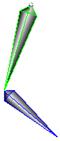
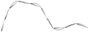
By default, bones do not render. They contain two types of display geometry: “link geometry” and “capture region geometry”. The former consists of a narrow diamond shape which has been stretched to the length specified in Bone Length, and placed along the Bone Object’s negative Z-axis. The latter consists of two or more user-controllable pill-shaped regions that are used to define capture regions used in skeleton sops. You can specify whether either of the two types of geometry are displayed.
The actual movement of the Bone objects is controlled through an IK CHOP (when using the standard Capture/Deform model). The IK CHOP overrides the bone rotation parameters. If you want to override this behavior, then you need to delete the bone’s channels such that they are no longer over-ridden by chop control.
When bones are parented as children of bone objects, they are automatically positioned at the tip of their parent bone object. If a bone object is parented as the child of a non-bone object, it will attach to the origin of the parent object.
Using Bones 
-
Click the

 Bones tool on the Characters tab.
 -
Click
 to place the chain of bones anywhere in the scene view, and continue clicking to add bones to the chain.
-
You can control interior snapping using the Placement menu in the operation toolbar. This is useful for snapping bones to the midline of character skin geometry.
By default, if a bone intersects a geometry node it will be placed within the geometry based on the view (“View based”). Otherwise the bone will be grounded on the construction plane.
“Normal based” snaps within geometry based on the geometry normals rather than the view.
“Freehand” does no interior snapping.
-
You can add, remove, and change kinematics in the drop-down menu on the operations toolbar, or click
 the bones in the scene view.
 If you create a chain of bones with inverse kinematics a
 null object will appear at the end of the chain which allows you to easily move the bones while it is grounded by the chain root.
-
-
Press Enter to finish the chain.
-
Name the chain of bones in the Chain Name field on the operations toolbar.
Using Bones 
-
In the viewport, press ⇥ Tab and type
 Path.
Path. -
Draw the curve in the viewport.
-
Make sure the curve is selected, and click the
 Bones from Curve tool on the Characters tab.
You can change the Kinematics to Follow Curve in the drop-down menu on the operations toolbar if you want the bones to be bound to the
 curve. This allows you to modify the curve and the bone chain is automatically adjusted.
 -
Name the chain of bones in the Chain Name field on the operations toolbar.
You can also increase or decrease the Number of Bones in the chain by changing the value in the value in the operations toolbar.
Parameters 
Transform 
Translate
Translation along XYZ axes.
Rotate
Degrees rotation about XYZ axes.
Uniform Scale
Scale the object uniformly along all three axes.
Modify Pre-Transform
This menu contains options for manipulating the pre-transform values. The pre-transform is an internal transform that is applied prior to the regular transform parameters. This allows you to change the frame of reference for the translate, rotate, scale parameter values below without changing the overall transform.
Clean Transform
This reverts the translate, rotate, scale parameters to their default values while maintaining the same overall transform.
Clean Translates
This sets the translate parameter to (0, 0, 0) while maintaining the same overall transform.
Clean Rotates
This sets the rotate parameter to (0, 0, 0) while maintaining the same overall transform.
Clean Scales
This sets the scale parameter to (1, 1, 1) while maintaining the same overall transform.
Extract Pre-transform
This removes the pre-transform by setting the translate, rotate, and scale parameters in order to maintain the same overall transform. Note that if there were shears in the pre-transform, it can not be completely removed.
Reset Pre-transform
This completely removes the pre-transform without changing any parameters. This will change the overall transform of the object if there are any non-default values in the translate, rotate, and scale parameters.
Keep Position When Parenting
When the object is re-parented, maintain its current world position by changing the object’s transform parameters.
Child Compensation
When the object is being transformed, maintain the current world transforms of its children by changing their transform parameters.
Enable Constraints
Enable Constraints Network on the object.
Constraints
Path to a CHOP Constraints Network.
Tip
You can you use the Constraints drop down button to activate one of the Constraints Shelf Tool. If you do so, the first pick session is filled automatically by nodes selected in the parameter panel.
Note
Lookat and Follow Path parameters on object nodes are deprecated in favor of ![]() Look At and
Look At and ![]() Follow Path constraints.
The parameters are only hidden for now and you can set their visibility if you do edit the node’s parameter interface.
Follow Path constraints.
The parameters are only hidden for now and you can set their visibility if you do edit the node’s parameter interface.
Bone 
Display Link
Toggles the displaying of the link geometry
Rest Angles
Defines the relative weighting of rotations about the bone’s x,y,z axis for the Inverse Kinematics solver. These values are relative to the bone’s pre-transform. These are zero by default when created from the object viewer’s Bones tool with the pre-transform rotation values defining the rest angles.
Bone Length
Changes the length of the bone
Kinematic Solver
Specifies the CHOP node from which this bone should obtain its cooking rotations from. This requires that the specified CHOP have 3 tracks that are named as: path:rx, path:ry, and path:rz where path is the full path of this bone without the /obj prefix. This path can be obtained using the opsubpath() expression function.
If this parameter is non-empty on a bone without custom geometry, then the display geometry of the bone will be different to indicate this.
The remaining parameters on this page only affect the solutions generated by InverseKin CHOPs using one of the solvers with constraints.
Dampening
Affects how quickly this bone’s angles can be changed.
Angle Range
Specifies the minimum and maximum rotation angles that this bone can have in each axis. (Only used by IK w/Constraints solver)
Damping Angle
Applies damping to the rotation of the bone when the rotation in each axis falls within the specified angle of its minimum or maximum value. The damping occurs when the solved angle is within this angle value from the angle range. (Only used by IK w/Constraints solver)
Damping Rolloff
Specifies the rate at which damping increases as the rotation varies within the damping angle of the minimum or maximum angles. This can also be thought of as the linear slope value at the damping angle region. (Only used by IK w/Constraints solver)
Capture 
Display Capture Region
Toggles the display of the /displaycapture capture region.
Capture Region 
Capture Region Center
Position of the center of the bone’s /ccrcenter[xyz] capture region. Note that this co-ordinate in object-space. Also the z component uses a bone length as a multiplier, thus 0.5 equals half way along the bone.
Capture Region Rotates
Rotation of the capture region /ccrrotate[xyz].
Capture Region Scales
Scaling factors. Scaling is performed about the bone local origin in the directions of the local reference frame axes. /ccrscale[xyz].
Capture Top Height
Height of the capture region from the /crtopheight center to the top cap.
Capture Top Cap
X,Y,Z radii of the top hemisphere /ccrtopcap[xyz].
Capture Bot Height
Height of the region from the center /ccrbotheight to the bottom cap.
Capture Bot Cap
X,Y,Z radii of the bottom hemisphere /ccrbotcap[xyz].
Deform Region 
This tab contains similar parameters as capture regions, but they are used for animation and deformation of captured geometry. Notably, the scaling factors can be used to squash and stretch the capture regions during animation.
Capture Bone Length
The length of a bone in the capture mode. This is the bone length when a bone is used for capturing geometry. Note that the capture mode can be turned on by selecting Edit ▸ Objects ▸ Bone Kinematic Override: Capture Pose from the main menu.
Capture Bone Translate
The translation of the bone in the capture mode.
Capture Bone Rotate
The rotation angles of the bone in the capture mode. Note that the bone rotation axis order is ZYX. Rotation together with Translate and Scale parameters form a transformation
that positions a bone in the capture position and orientation with respect to the world space. The transform order for this transformation is Scale, Rotate, Translate.
Capture Bone Scale
The scaling of the bone in the capture mode.
Render 
Display
Whether or not this object is displayed in the viewport and rendered. Turn on the checkbox to have Houdini use this parameter, then set the value to 0 to hide the object in the viewport and not render it, or 1 to show and render the object. If the checkbox is off, Houdini ignores the value.
Misc 
Set Wireframe Color
Use the specified wireframe color
Wireframe Color
The display color of the object
Viewport Selecting Enabled
Object is capable of being picked in the viewport.
Select Script
Script to run when the object is picked in the viewport. See select scripts .
Cache Object Transform
Caches object transforms once Houdini calculates them. This is
especially useful for objects whose world space position is
expensive to calculate (such as ![]() Sticky objects),
and objects at the end of long parenting chains (such as
Sticky objects),
and objects at the end of long parenting chains (such as
![]() Bones). This option is turned on by default for Sticky and
Bone objects.
Bones). This option is turned on by default for Sticky and
Bone objects.
See the OBJ Caching section of the Houdini Preferences window for how to control the size of the object transform cache.
| See also |