Houdini 22.0 Copernicus

Adjacency

Describes how to use adjacency nodes in your network.

On this page

Overview

Adjacency COP nodes help with image processing over texture seams. The adjacency system helps by storing information on how to find pixels that live on adjacent UV islands. Adjacency COP nodes can also create seamless textures from geometry attributes.

Note

Adjacency workflows output the best results when the texture of the target matches that of the rasterized adjacency maps.

Adjacency workflows require an adjacency cable, which you can create from a geometry using the Geometry to Adjacency COP. This cable contains the rasterized geometry that you can then wire into other adjacency COP nodes for processing.

Use adjacency nodes to do the following:

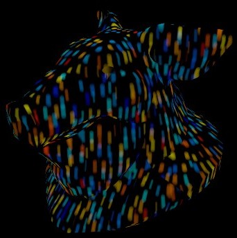
With adjacency.
Without adjacency.

The following COP nodes also support adjacency cables:

Examples of using adjacency nodes

To...Do this

Create an adjacency cable

  1. Create geometry in your Copernicus network. For example, create a Test Geometry: Pig Head.

    Tip

    Create geometry using the SOP Import COP (see Bringing SOPs into COPs) or a Test Geometry COP.

  2. Add a Geometry to Adjacency COP and wire the Pig Head into its geometry input.

  3. Set the Geometry to Adjacency’s UV Attribute to the UV channel you want to rasterize. For example, uv.

You now have an adjacency cable that you can use with adjacency nodes.

Create a seamless 3D texture map

  1. Create an adjacency cable.

  2. Add an Attribute Sample with Adjacency COP and wire the Geometry to Adjacency COP into its adjacency input.

    Tip

    Use the attrib input to sample a point attribute from another geometry.

  3. Configure the Attribute Sample with Adjacency COP with the attribute you want to rasterize. For example, P for world position.

  4. Add a Fractal Noise 3D COP and wire the Attribute Sample with Adjacency COP into its pos input. The rasterized attribute (P in this example) drives the 3D noise to get the texture map.

    Note

    If your geometry has n-gons and you sample attributes from that geometry, there may be unwanted distortion in your workflow.

You now have a texture map without any seam discontinuities.

Transform vectors into the desired space

  1. Create an adjacency cable.

  2. Add a Space Transform with Adjacency COP and wire the Geometry to Adjacency COP into its adjacency input.

  3. Wire the vector that you want to transform into the Space Transform with Adjacency’s coord input. For example, wire in a Constant COP with its Signature set to RGB and Color set to (0, -1, 0).

  4. Configure the Space Transform with Adjacency COP so it transforms the vector into the desired space. RGB outputs the full vector and UV outputs only the X and Y components of the vector. For example, set Signature to UV and Transformation to World to Tangent.

    Tip

    You can wire the Space Transform with Adjacency COP into a Normalize node to normalize the vector before you connect it to the rest of the workflow.

You now have vectors facing the desired direction for your geometry that you can use in the workflow to drive UV or RGB inputs (such as direction).

Distort over a geometry’s texture seams

  1. Create an adjacency cable.

  2. Add a Distort with Adjacency COP and wire the Geometry to Adjacency COP into its adjacency input.

  3. Wire the layer that you want to distort over the geometry’s texture seams into the Distort with Adjacency’s source input. For example, wire in a Ramp Mono COP.

    Tip

    You can wire in a dir input to trace through vectors of a UV layer. The node uses this input instead of the Direction parameter’s value to distort the layer in a texture space direction.

  4. Configure the Distort with Adjacency COP so it distorts the layer’s pixels in the desired direction.

You now have geometry with distortion along its texture seams.

Extend UV island borders using neighboring islands

  1. Create an adjacency cable.

  2. Add a Block and configure the Block Begin COP with the following input:

    • Input Name: adjacency

    • Input Type: Cable

  3. Wire the Geometry to Adjacency COP into the Block Begin’s adjacency input.

  4. Add and wire an Extrapolate with Adjacency COP between the output and input of the block. This node gives each UV (texture) island in the cable information by moving neighboring islands' information to the original UV islands' borders.

    Tip

    Turn on Transform Vectors between Islands to also transfer pixel vector information between islands when you're working with velocity fields and normals. This reorients the vector direction to match the rotation of neighboring islands.

  5. Add and wire a Dilate Erode COP between the output of the Extrapolate with Adjacency COP and input of the Block End COP.

  6. Configure the Dilate Erode COP to the following:

    • Units: Pixels

    • Radius: 5

You can now run the block for a few iterations to spread the dilation over the entire surface.

Advanced

Use the Cable Unpack COP to view the following contents of the adjacency cable:

  • uv_adjacency outputs the rasterized UV channel.

  • primid outputs the primitive ID channel.

  • primuv outputs the primitive UV channel.

  • mask outputs the mask channel.

  • N outputs the normals.

  • tanU outputs the U tangent vector for the UV channel.

  • tanV outputs the V tangent vector for the UV channel.

  • uv_derivative outputs the derivative of the UV channel.

  • tangent_xform outputs the tangent channel.

  • uvscale outputs a scaled version of the UV channel.

  • geo outputs the base geometry.

See also

Copernicus

Basics

Next steps

  • Slap comp

    Slap composite (slap comp) is a fast image manipulation you can use to view approximate and live results of a final composite.

  • Copernicus heightfields and terrains

    Create realistic terrains with Houdini’s Copernicus heightfield tools.

  • OpenFX

    Describes what OpenFX is and how to use it in your network.

  • Hatching

    Describes how to use hatching in your Copernicus network.

  • VDBs

  • Adjacency

    Describes how to use adjacency nodes in your network.

  • Filter List

    The Filter List window lets you quickly apply effects in your scene.

  • Copernicus tips

    Useful tips and information while using COPs.

Dynamics

Machine Learning

Advanced concepts

  • Normals

    Defines the normals that the Copernicus network uses.

  • Spaces

    Defines the spaces that the Copernicus network uses.