| On this page |
Overview 
Sometimes you want to transition agents to a state where instead of being controlled by animation, they are controlled by a rigid body simulation. For example, if an agent dies, you want it to fall to the ground, with its body and limbs being knocked around by collisions.
Setting up a ragdoll scene 
Use the Simulate shelf tool to quickly get a basic crowd simulation scene up. Then tweak the network for your purposes.
-
Press ⌃ Ctrl +
 on the
  Simulate tool on the Crowds shelf tab. The tool will automatically build agents and a crowd source network using the
  mocapbiped1 character built into Houdini.
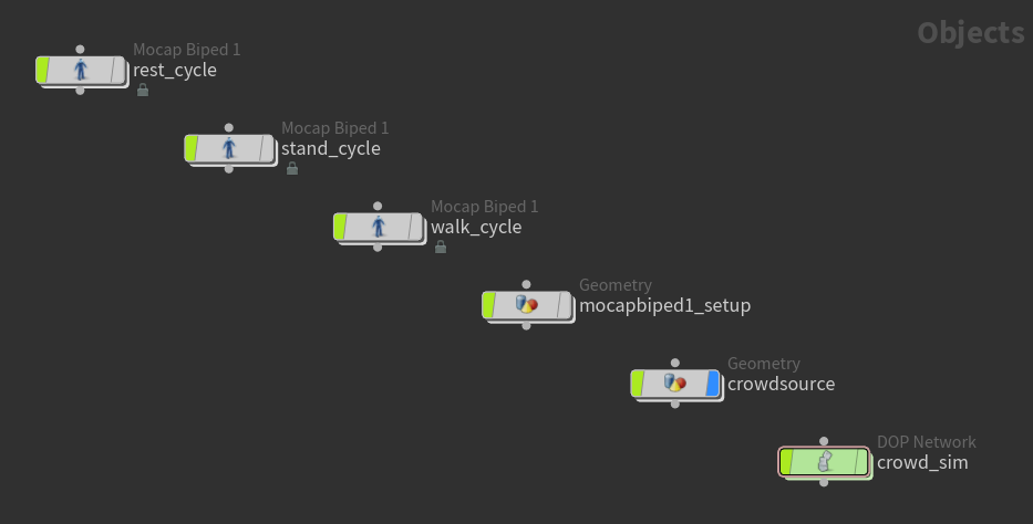
Object-level network created from the Simulate shelf tool The crowd simulation network (
crowd_sim) created by the Simulate shelf tool: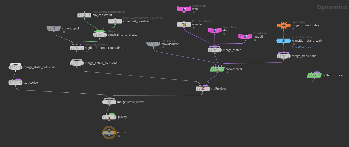
Crowd simulation DOP network -
Play the simulation by clicking
 Play on the playbar. The agents will stand, and then walk.
 -
In the current scene, the agents only transition from the “stand” state to the “walk” state. Add another trigger to transition the agents from the “walk” state to the “ragdoll” state.
-
Add a
 Crowd Trigger DOP and
  Crowd Transition DOP.
 -
In the new Crowd Transition DOP, set Input State to
walk, and Output State toragdoll.
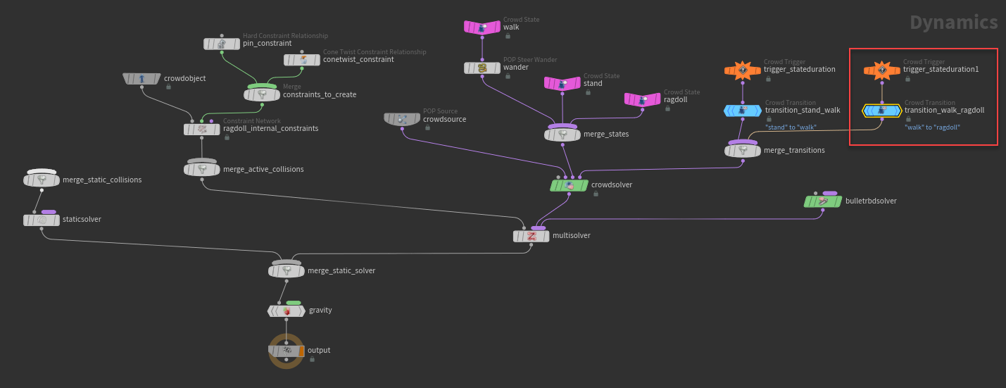
Add a transition to the ragdoll state -
-
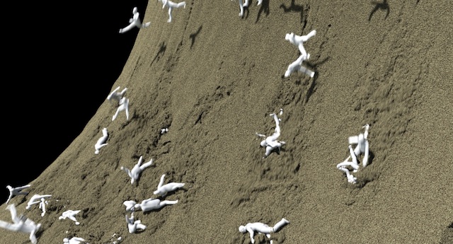
Play the simulation. The agents will stand, walk, and then fall through the scene, because they have nothing to collide against.
-
Add a ground plane (
 Ground Plane DOP) for the agents to collide against. Connect the Ground Plane DOP to the
 merge_static_collisionsnode. -
Play the simulation. The agents will stand, walk, and then fall on the ground as ragdolls.
Agent setup ragdoll 
The Simulate shelf tool sets up an agent definition network (mocapbiped1_setup), a geometry network that defines the agents in a crowd simulation.
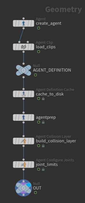
The ragdoll-specific information in the agent definition network are:
-
Collision shapes (
 Agent Collision Layer SOP) - Defines simple geometry around the agent’s skeleton that are used to determine the surfaces to collide against when the agent becomes a ragdoll.
 -
Configure joints (
 Agent Configure Joints SOP) - Specifies the range of motion for each joint.
Collision shapes 
Collision shapes define simple geometry around the agent’s skeleton that are used to determine the surfaces to collide against when the agent becomes a ragdoll.
-
In the agent definition network, select the
Agent Collision Layer node and turn on its display flag. -
Turn on the
 Show Handle tool to the left of the viewport.
 -
In the viewport, click on the blue markers to attach a collision shape to that part of the agent. Once you click on a blue marker, the collision shape is added to the list of Collision Shapes in the Agent Collision Layer parameters.
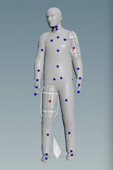
Collision shapes in the viewport -
Change the location, orientation, and size of the collision shape by using the collision shape handles in the viewport, or by editing the Agent Collision Layer’s Collision Shapes parameters in the parameter editor.
-
Hover over the viewport and press Z to cycle through the available shapes to use as the collision shape. You could also change the shape in the Agent Collision Layer’s Shape parameter for each collision shape.
Note
If you don’t need to separately simulate all the finger joints, you can use a single collision shape for the whole hand. This can be done by attaching the shape to a parent joint of the hand (for example, the wrist), and then adjusting the shape to cover the hand. Attaching the shape to a parent joint is important so that the child joints (fingers) inherit the wrist joint’s motion.
With fewer simulated joints, there is less work to setup and configure the collision shapes and joint limits, and will also result in faster performance.
| To... | Do this |
|---|---|
|
Change the collision shape assigned to a joint |
|
|
Delete a collision shape |
In the viewport, click on a red marker and press Delete. |
Configure joints 
The ![]() Agent Configure Joints node specifies the range of motion for each joint. This is where you configure, for example, that a character’s elbow cannot bend backward.
Agent Configure Joints node specifies the range of motion for each joint. This is where you configure, for example, that a character’s elbow cannot bend backward.
-
In the agent definition network, select the Agent Configure Joints node and turn on its display flag.
-
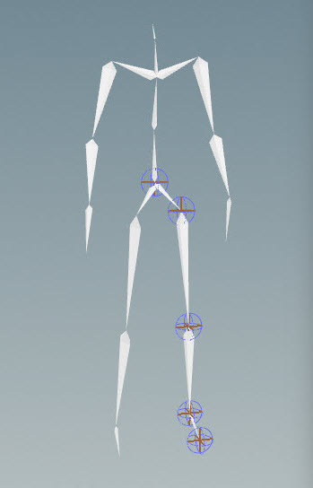
In the viewport, click on the blue markers to add joint limits to that part of the agent. Once you click on a blue marker, the joint limits are added to the list of Joint Limits in the Agent Configure Joints parameters.
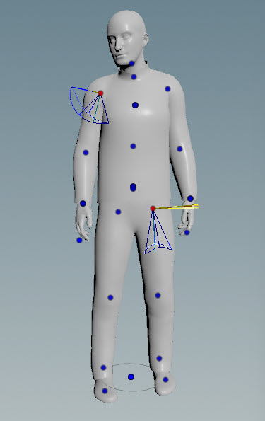
Joint limits in the viewport Note
In the toolbar above the viewport, there is a Limit Selection to Collision Layer option. When turned on, only the joint markers that have a collision shape attached are displayed and available to select (collision shapes are defined by the prior Agent Collision Layer SOP). Generally, you would only need joint limits for joints that have a collision shape attached.
If you first set up collision shapes, and then configure joint limits, turn on Limit Selection to Collision Layer so that only the relevant joints (the ones with collision shapes attached) are displayed. On the other hand, if you are setting up the joint limits first, turn off Limit Selection to Collision Layer, which allows you to select any joint in the skeleton.
-
Adjust the joint limits using the joint limit handles in the viewport, or by editing the Agent Configure Joints' Joint Limits parameters in the parameter editor.
| To... | Do this |
|---|---|
|
Delete a joint limit |
In the viewport, click on a red marker (denoting a joint with a joint limit configured) and press Delete. |
|
Create a hinge (like an elbow or knee) |
For the Up Rotation Range or Out Rotation Range parameters, set the minimum and maximum values to 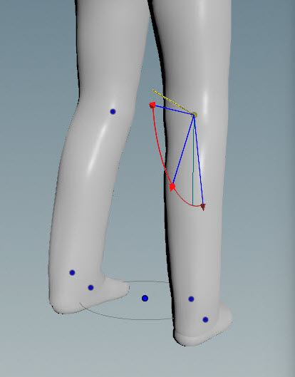
|
Joint groups 
Create named groups of joints on the agent so that you can apply ragdoll effects to some parts of the agent and not others.
-
Place an
 Agent Transform Group SOP after the Agent Configure Joints SOP.
 -
In the parameter editor, use the Transform Groups multiparm to create new groups. For each group:
-
Set the Name to the name of the joint group. For example,
upper_body. -
In Root Transforms, select the root joint(s) for the group. Each root and its descendants will be added to the group.
-
To control how much the ragdoll effects (such as stiffness) apply to the root versus the “outermost” joints, turn on Blend into Group.
-
To see the joints that are part of the group, turn on Show Guide Geometry, which displays spheres around the selected joints. You can change the size of the spheres on the Guides tab. Display the agent as Wireframe to more easily see the guide geometry.
Guide geometry displayed for the left leg joint group -
Testing 
Place a ![]() Test Simulation Ragdoll node after the Agent Collision Layer, Agent Configure Joints, or Agent Transform Group node. Turn on the display flag of the Test Simulation Ragdoll node, and click
Test Simulation Ragdoll node after the Agent Collision Layer, Agent Configure Joints, or Agent Transform Group node. Turn on the display flag of the Test Simulation Ragdoll node, and click ![]() Play in the playbar to play a simple simulation of the agent in a ragdoll state with gravity.
Play in the playbar to play a simple simulation of the agent in a ragdoll state with gravity.
Tip
This node can help you figure out whether the joint limits have been set up correctly. Turn off the Allow Initial Violation of Limits parameter in the Constraints tab. If the skeleton’s initial state is outside the joint limits when you start the simulation, the joint(s) will immediately pop, showing you where there is an issue.
| To... | Do this |
|---|---|
|
Test how the agent reacts when you throw it in different directions |
|
Ragdolls in DOPs 
In the crowd simulation network, you can set the states when agents are ragdolls, and the triggers that cause the agents to become ragdolls.
Ragdoll state 
Choose to make agents in a particular state become ragdolls by setting the ![]() Crowd State DOP RBD Ragdoll parameter to one of the following:
Crowd State DOP RBD Ragdoll parameter to one of the following:
Active
Agents are simulated as ragdolls, as opposed to following an animation clip.
Animated Static
Agents are not ragdolls; their motion follows an animation clip. They can affect other simulated objects (for example, kicking things around as they walk), but simulated objects do not affect the agent.
Ignore
Agents are not ragdolls, and no rigid body dynamics objects will collide against the agents.
See the ![]() Crowd State DOP for more information.
Crowd State DOP for more information.
Trigger to ragdoll state 
Set the trigger that causes the agents to become ragdolls with the ![]() Crowd Trigger DOP. This could be used, for example, to change walking agents to ragdolls when they are hit by a boulder.
Crowd Trigger DOP. This could be used, for example, to change walking agents to ragdolls when they are hit by a boulder.
| To... | Do this |
|---|---|
|
Trigger a state transition when an agent is hit by an RBD object |
|
|
Trigger a state transition when agents collide with other agents |
Set the crowd object ( |
Ragdoll effects 
When agents are in the ragdoll state (RBD Ragdoll parameter set to Active on the ![]() Crowd State DOP), you can apply effects to the agents such as:
Crowd State DOP), you can apply effects to the agents such as:
-
Sticky collisions - Configure objects to stick to agents during a collision.
-
Stiffness - Control the resistance to changes in the agent’s pose.
-
Partial ragdoll - Part of the agent can be simulated while the rest follows an animation clip.
-
Motors - Joints can be partially driven by an animation clip, but still react to simulation forces.
See the ![]() Crowd State DOP for more information.
Crowd State DOP for more information.
Sticky collisions 
Consider the scenario where arrows are being shot at a crowd of agents. When the agents are hit, they turn into ragdolls and fall to the ground. In this case, you would want the arrows to stick to the agents, and not bounce off and fall away. This is where sticky collisions come in.
Sticky collisions can be configured for each state that the agents are in. For example, you can configure sticky collisions such that the arrows stick to the agents when they are walking, but not when they are in a ragdoll state. This is done by setting the sticky collisions parameters in the ![]() Crowd State DOP.
Crowd State DOP.
You can also trigger new agent behavior (trigger a new state) based on the number of sticky collisions that have occurred on an agent. The ![]() Crowd Trigger DOP has an option that counts the number of sticky collisions that have occurred on an agent, and uses it to trigger new behavior.
Crowd Trigger DOP has an option that counts the number of sticky collisions that have occurred on an agent, and uses it to trigger new behavior.
In the video below, arrows that hit the agents get stuck onto the agents. When an agent is hit with two sticky collisions, they transition from a walking state to a ragdoll state.
Sticky collisions is also a feature on the bullet solver. So in our example above, the agents can be sticky, but the arrows can also be sticky. You can configure RBD objects (arrows) to be sticky using the ![]() RBD Configure SOP. If you have sticky collision settings on multiple objects, the settings can override each other. For example, the object with the higher collision impact threshold would take precedence. See sticky collisions on the bullet solver for more information about the sticky collision settings that are shared between the RBD Configure SOP and the Crowd State DOP.
RBD Configure SOP. If you have sticky collision settings on multiple objects, the settings can override each other. For example, the object with the higher collision impact threshold would take precedence. See sticky collisions on the bullet solver for more information about the sticky collision settings that are shared between the RBD Configure SOP and the Crowd State DOP.
| To... | Do this |
|---|---|
|
Set specific parts of the agent to be sticky |
On the |
|
Control the stickiness of the agents |
On the Crowd State DOP, the Min Collision Impulse parameter defines the minimum impact from a collision that will cause an object to stick to the agent. A higher number makes it harder for an object to stick to the agent. Min Collision Impulse must be set to a value greater or equal to 0 for objects to stick to the agent. |
|
Restrict the number of objects that can stick to each agent |
On the Crowd State DOP, set Max Collision Objects per Shape to the number of objects that can stick to each collision shape on the agent joint group that is specified as being sticky. See collision shapes for defining collision shapes for an agent. To visualize the collision shapes on the agents, on the
For example, if the In the image below, collision shapes are shown for an agent’s upper body. If Max Collision Objects per Shape is set to 2, the bottom red arrow would not stick to the agent, because it will hit the same collision shape that already has 2 objects stuck to it. 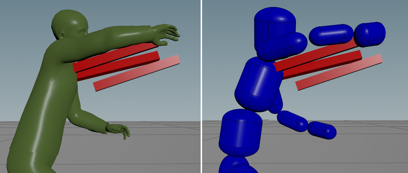
|
|
Avoid swinging objects |
By default, the bullet solver creates glue constraints for sticky collisions, which produces a perfectly rigid attachment between the colliding objects. If you switch the constraint type to a soft constraint, this would allow an object that hits an agent to swing around the anchor (contact) point. To avoid this behavior, increase Max Collision Points on the Crowd State DOP to add more contact points between the object and agent. |
|
Only allow specific objects to stick to the agents |
On the Crowd State DOP, set Collision Ignore to the objects you don’t want to stick to the agents. The objects listed here will collide with, but not stick to, the agents. You can specify the following in Collision Ignore:
|
|
Trigger a new behavior based on the number of sticky collisions that have occurred on an agent |
For example, if Transform Group is set to In the below image, the green agents are in the walking state and have not been hit on the upper body with 2 sticky collisions. A few frames later on the right, the yellow agents have been hit on the upper body with 2 sticky collisions and have become ragdolls. 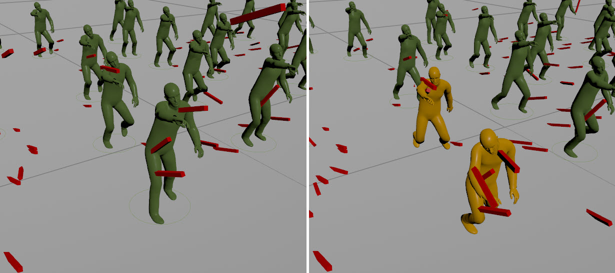
|
Troubleshooting 
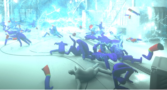
In the video below, the constraints holding the ragdoll agents together are disabled when the walking agents collide with the ragdoll agents. Sticky collisions are turned on for the walking agents.
Glue constraints are created by the bullet solver for sticky collisions. When the agents collide, the bullet solver creates glue constraints to stick the agents to each other.
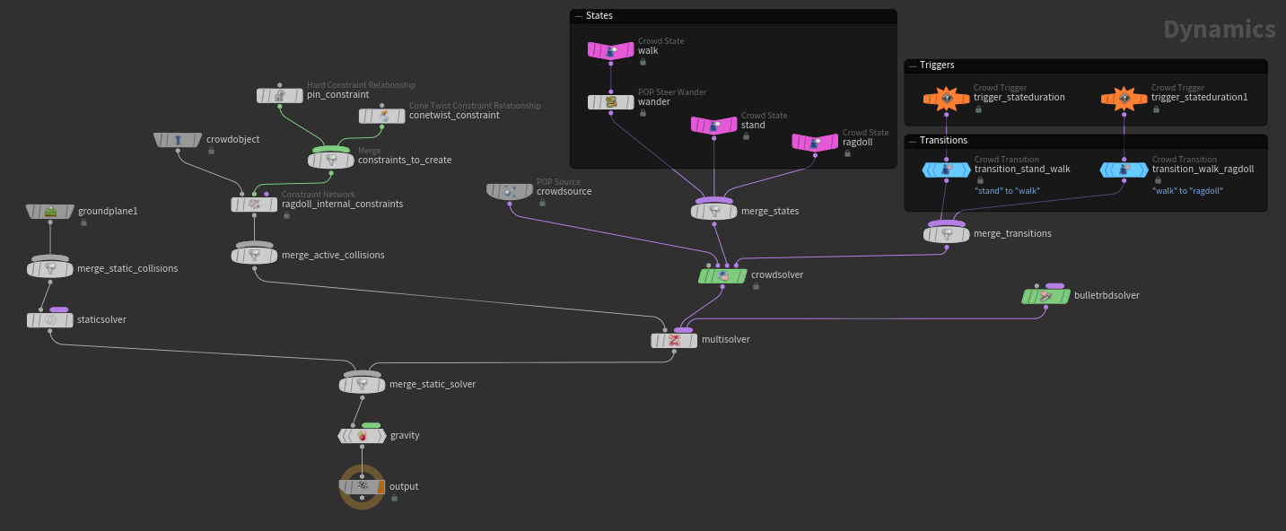
When the glue constraints are created, they are added to one of the constraint networks within the DOP crowd simulation network. Constraint networks define the pairs of rigid body objects that should be constrained together. In this case, the DOP network contains two ![]() Constraint Network DOPs -
Constraint Network DOPs - ragdoll_constraints and rbd_to_agent_constraints.
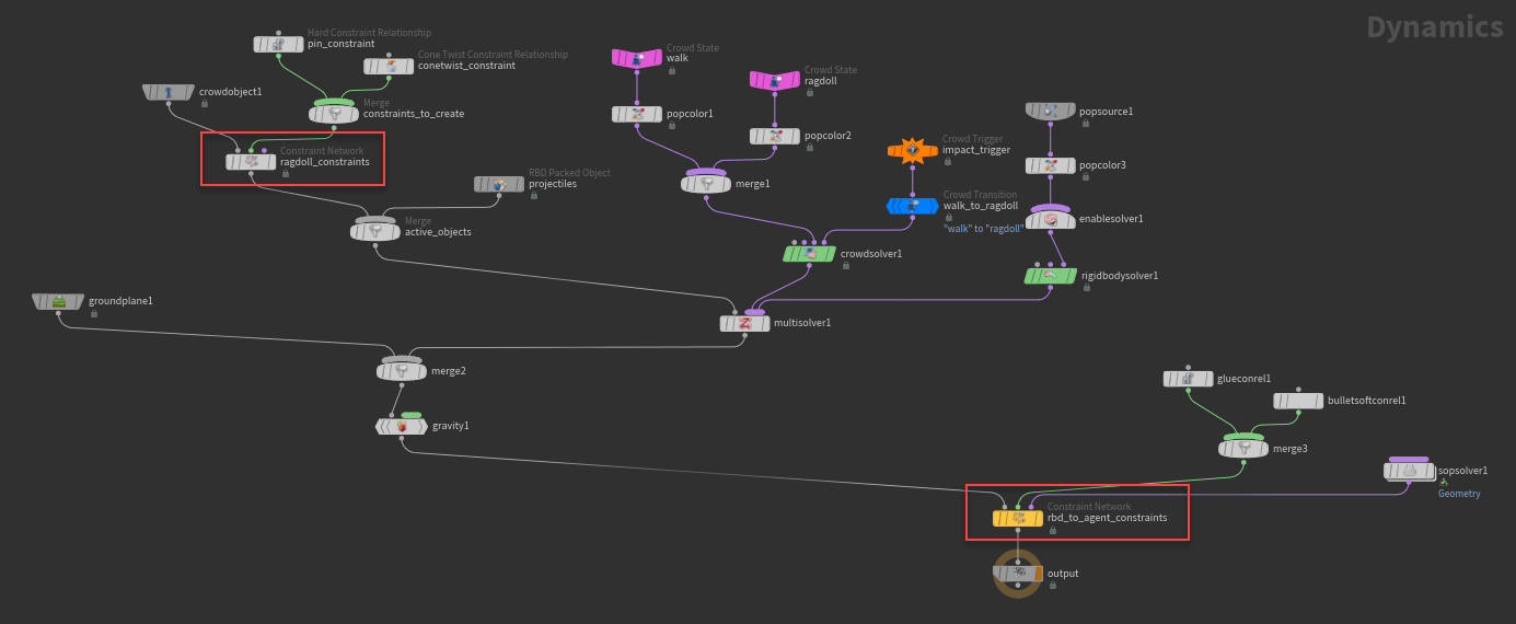
ragdoll_constraints constraint network
Defines the constraints between the agents. Does not have a glue constraint wired into its 2nd input (we will see why this is important later).
rbd_to_agent_constraints constraint network
Defines the constraints between the arrows and agents. Has a glue constraint wired into its 2nd input.
The bullet solver’s logic for deciding the constraint network to add the sticky collision constraints to is controlled by the Sticky Collisions parameters on the ![]() Bullet Solver DOP. (In the network above, the bullet solver is the
Bullet Solver DOP. (In the network above, the bullet solver is the ![]() Rigid Body Solver DOP (
Rigid Body Solver DOP (rigidbodysolver1) with its Solver Engine parameter set to Bullet.)
In this example, the bullet solver added the sticky collision constraints to the ragdoll_constraints constraint network, because:
-
The collision was between two rigid bodies (agents) that were both in the crowd object (
crowdobject1)and
-
The Use Internal Constraint Networks parameter on the bullet solver was turned on. This caused the sticky collision constraints to be added to the constraint network (
ragdoll_constraints) between the colliding objects (agents).
Constraint networks need to have the appropriate constraint type wired into its 2nd input. In this case, the glue contraints created from the sticky collisions were added to the ragdoll_constraints constraint network, but ragdoll_constraints did not have a glue constraint wired in (unlike rbd_to_agent_constraints). This caused an error on ragdoll_constraints, which in turn, disabled the conetwist constraints that were holding the ragdoll together.
Solutions
There are a few solutions, depending on the behavior you want:
-
If you don’t want the agents to stick together, set the walking agents to ignore collisions with other agents - in the Crowd State DOP for the
walkstate, set Collision Ignore tocrowdobject1(the agents). -
If you want all the sticky collision constraints (between an arrow and agent, and between two agents) to be in the
rbd_to_agent_constraintsconstraint network, turn off Use Internal Constraint Networks on the bullet solver. Otherwise, the sticky collision constraints will be added toragdoll_constraints.If you have additional constraint networks in your DOP network, explicitly specify that the sticky collision constraints are to be added to
rbd_to_agent_constraintsby setting External Constraint Network on the bullet solver torbd_to_agent_constraints. -
If you want the sticky collision constraints between two agents to stay in the
ragdoll_constraintsconstraint network, either wire in a glue constraint into the 2nd input ofragdoll_constraints, or add a SOP solver to switch the new sticky collision constraints to another constraint type, like hard or soft constraints.
Note
Deciding which constraint network to put the sticky collision constraints in is a workflow choice. However, in the above example, the Attach Internal Constraints to Objects parameter in the ragdoll_constraints constraint network is turned on by default, which means that ragdoll_constraints can only contain constraints between two agents, and not constraints between an arrow and an agent.
See bullet solver and constraint network for more information.
Stiffness 
When stiffness is turned on, agents try to keep their current pose once they become ragdolls. When stiffness is turned off, agents have a floppy behavior in their ragdoll state.
| To... | Do this |
|---|---|
|
Turn on stiffness |
|
|
Increase stiffness |
On the Crowd State DOP under the Stiffness section, increase the Stiffness parameter. The Stiffness parameter is available when Stiffness Value is set to Constant. |
|
Increase the stiffness for specific parts of the agent |
On the Crowd State DOP under the Stiffness section, set the Group parameter to the group of joints you want to increase the stiffness for. See joint groups for how to create groups of joints on the agent. |
|
Control the stiffness over the first few seconds that the agents are in the current state |
|
Partial ragdoll 
With partial ragdoll turned on, you can specify part of the agent to be a ragdoll, while the rest of the agent follows an animation clip. For example, you can have the lower body animated by a walking clip, while the upper body is a ragdoll and reacts to hits from simulated objects.
In the below video, the agents' upper bodies becomes ragdolls once the upper body is hit with a sticky collision, while the lower body continues walking based on an animated walking clip.
| To... | Do this |
|---|---|
|
Specify certain parts of the agent to be a ragdoll |
|
|
Specify the animation clip to play for the non-ragdoll part of the agent |
|
|
Increase the speed of the animation clip |
|
Tip
If the agent’s feet appear to slide around once they transition to the ragdoll state, change the Type to Locomotive under the Clip Playback section. This will cause the agent’s movement to be guided by the clip’s locomotion data. If Type is set to In-Place, the agent’s movement is driven entirely by the underlying particle, which could cause the agent’s foot placement to slide around instead of being planted on the ground with each step.
Motors 
When the motors effect is turned on, the agent joints are partially driven by an animation clip, but will still react to simulation forces.
In the below video, once the agents turn to ragdolls, their legs are still partially driven by the walking animation clip.
| To... | Do this |
|---|---|
|
Turn on the motors effect |
|
|
Increase the effect of the animation clip |
On the Crowd State DOP under the Motors section, increase the Motor Strength parameter. The Motor Strength parameter is available when Strength Value is set to Constant. |
|
Specify certain parts of the agent to be driven partially by an animation clip |
On the Crowd State DOP under the Motors section, set the Group parameter to the group of joints you want to be partially animated by the clip. See joint groups for how to create groups of joints on the agent. |
|
Control the effect of the animation clip over the first few seconds that the agents are in the current state |
|
Detaching limbs (advanced) 
-
The
 Agent Constraint Network node in the crowd source geometry network creates a set of polylines representing every constraint for every joint on every agent. The
 ragdoll_constraints Constraint Network DOP in the crowd simulation network imports these constraints into the simulation, and the
  bullet solver applies forces to maintain the constraints.
You can append a
SOP Solver to the multisolver to modify the constraints as part of the simulation (such as deleting constraint lines to detach limbs). The constraints are stored in the crowd object’s ConstraintGeometrysubdata, so the SOP Solver’s Data Name parameter should be set toConstraintGeometryinstead of the default value (Geometry). -
If you have agents that are ragdoll (RBD Ragdoll parameter on their state is set to Active) or can potentially switch to ragdoll (RBD Ragdoll is set to Animated Static), the ragdoll solver adds attributes to the constraints you can use to trigger constraint changes.
 click the
 relationship_geometrynode in the SOP solver network and choose Spreadsheet to see the attributes. -
The
torqueprimitive attribute contains the force the solver had to use to maintain the constraint in the current timestep (in other words, the amount of force on the joint).To detach limbs upon impact, set up a primitive wrangle that deletes constraint lines where the
torqueis above a certain limit:if (f@torque > 50) removeprim(0, @primnum, /* andpoints */ 1);
-
If you have deforming geometry on the agent, the detached part will move away, but the skin will stretch over the detached part. You need to switch to an alternate layer with separate skin geometry for detached agents.