| On this page |
|

This, more complex, project shows how to create a feather with separated vanes in a so-called uncondensed state. In this state, the barbs consist of real curve geometry with points. There are several differences to a condensed workflow with virtual barbs. You can choose the best solution for your feathers, but we recommend using only one method when you create a feather atlas. In this uncondensed example
-
the feather is split into separate networks for shaft, left and right barbs
-
the
 Guide Process SOP operations are applied to Curves
 -
clumping is achieved through a
 Hair Clump SOP
 -
the network uses a
 Feather Uncondense SOP
 -
 Attribute Wrangle SOPs identify the barb curves.
Down isn’t like other feathers, because they have a different barb structure. There’s completely irregular down and transition forms with more or less structured parts. Down also have a rather short and more elastic shaft. Despite the diverse appearance and characteristics of down, there are also a couple of common features. Fluffy down barbs
-
don’t have barbules - the tiny hooks that keep the barbs together
-
aren’t regular to pocket air and keep the bird warm
-
are soft.
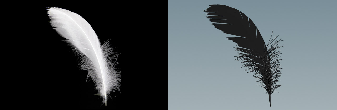
Reference image 
Everything starts with a reference image and there are many free resources with excellent photos of various feather types.

Note
In many countries it’s not allowed to collect bird feathers, even if you find a single feather on the ground. This is to prevent birds from being killed for their feathers and protect endangered species. You should therefore only use photos from repositories.
The feather in this project is a typical transition form. The down has fluffy and regular parts, and even a mixed zone in the area near the bottom. There you can see long structures, growing between regularly arranged barbs. Some of these fluffy barbs are also shorter near the bottom. Furthermore, the down’s tip on the left side is frayed, while the barbs on the right side have almost the same length. The left side also shows more gaps and splits. The shaft has the same width throughout its entire length.
To load the reference image, do the following.
-
Move the mouse cursor over the viewport and press 2 to switch to top view. You can create feather’s only in Houdini’s XZ space!
-
Now press D to open the Display Options.
-
Open the Background tab, then click the Top tab.
-
Make sure that Disk File is turned on and click the
 icon to load a reference image.
 -
Use the Image Offset and Image Scale parameters to position and scale the reference image. Mind the feather’s original scale.

Tracing the feather 
Note
All steps and nodes you need trace a feather’s shape from a reference image, are explained on the Drawing a Feather page. Follow the drawing guide until Profiles (inclusive), then return to this page and proceed with Creating the down.
The workflow for tracing a feather is the same for all types of feathers.
-
Feather curves are always located inside a
 Geometry OBJ level. Go to the obj level and select the Geometry SOP. Open its Misc tab and turn on Shade Open Curves in Viewport to make the barbs visible. Then dive inside the Geometry node again to proceed.
 -
Use the
 Curve SOP to draw the feather’s shaft and boundaries. Beziers or NURBS are best suited here.
 -
Refine the curves to get the final shape.
-
Add profiles to shape the barbs according to the reference image.
Creating the down 
The next step groups the curves before you can turn them into a feather.
-
Add a
 Feather Shape Organize SOP.
 -
Connect its first input with the output of
curve1.The node doesn’t have any parameters, but you can open the Geometry Spreadsheet and click the
 icon to see the
 shaftandshapegroups it creates. -
Lay down a
 Feather Template from Shape SOP and connect its input with the shape organizer’s output. You should see a solid object with an UV grid.
Adjusting the barbs 
You might have noticed that the number of barbs is insufficient and there’s a visible alias effect, because the barbs are very thick. All changes are made on the Feather Template from Shape SOP.
-
To make the barbs thinner and get rid of the alias effect, change both Width Root and Width Tip to
0.0003. -
You can fix the “skeleton” look with a Barb Density of
5000. Now you have a dense feather with enough detail. -
Finally, increase Barb Segments to
5to get a smoother curvature.
The left image shows the reference for comparison. In the middle you can see the curves, and on the right the barbs.

Uncondensing 
To convert the virtual (=condensed) barbs into real geometry, you need just one node.
-
Add a
Feather Uncondense SOP. -
Connect its first input to the upstream
Feather Template from Shape SOP. The first output is linked to the input of a  Merge SOP or
  Null SOP.
When you open the Output Groups section, you can see two toggles. Turn them on to separate the feathers' left and right barbs from the shaft. You can see that Right Barbs Group depends on Left Barbs Group. Both are combined inside a common
barbsgroup. If you don’t want to work on the feather’s left and right barbs separately, you don’t have to change anything. Otherwise, do the following. -
Right-click Right Barbs Group. From the menu, choose Delete Channels to separate the parameters.
-
For Left Barbs Group, enter
barbsl. -
For Right Barbs Group, enter
barbsr.
The feather is now separated into three groups: shaft, barbsl and barbsr.

Barb indices 
Barb indices are often necessary to further subdivide the barbs into groups.
-
Lay down an
 Enumerate SOP and connect its input with the output of the upstream Feather Uncondense SOP.
 -
Keep the default values, but make sure that Group Type is set to Primitives.
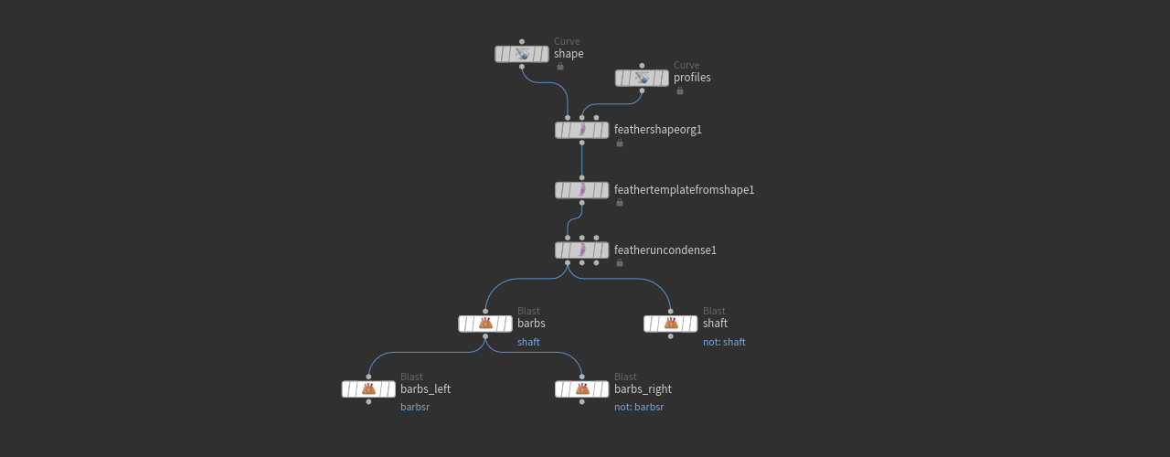
Isolating shaft and barbs 
The Feather Uncondense SOP creates three groups: shaft, barbsl and barbsr. In order to work on each group separately, you must isolate the feather’s elements and create separate network streams.
Tip
With Houdini’s default blue background it can be difficult to see and evaluate the result of your operations. It can be helpful to add a ![]() Color SOP and make it always the last node in the network. Set its Color to black (or any other color) to enhance the feather’s contrast and visibility.
Color SOP and make it always the last node in the network. Set its Color to black (or any other color) to enhance the feather’s contrast and visibility.
-
Add two
 Blast SOPs and connect their inputs with the first output of the Feather Uncondense SOP. Don’t daisy-chain the Blast nodes; they create two streams.
 -
Rename the first node to
barbs, the second one toshaft. -
Select the first Blast SOP and go to the Group parameter. There, enter
shaftto delete/blast the shaft and keep the barbs. -
On the second Blast SOP, the Group is also
shaft. Then, turn on Delete Non Selected to remove the barbs.To separate the barbs into left and right, you need two more Blast SOPs.
-
Add two more Blast SOPs and name them
barbs_leftandbarbs_right. -
The Group entry for both nodes is
barbsr. -
On the
barbs_rightblast node, turn on Delete Non Selected. -
Connect the new blasts' inputs to the outputs of the
barbsnode. Again, don’t daisy-chain the two nodes, because they also create two streams.
Now you can work on all parts independently. Your network should look as illustrated here.
The shaft 
The shaft is the feather’s third element that must be addressed. Currently, the shaft is just a thin line, but in the real world, it tapers from bottom to top. The most convenient way uses a ![]() Feather Width SOP.
Feather Width SOP.
-
Add the Feather Width SOP and connect its first input with the output of the
shaftblast. If there’s already a Merge SOP, connect the width node’s first output to the merge. -
With Shaft Width you can apply a uniform value to the shaft. To create the tapering effect, click the Ramp button.
-
Click the
 Presets icon and choose Smooth from the dropdown menu. Right now the tip is thick and the base is thin.
 -
Click the
 Reverse Domain to invert the ramp.
 -
You can add more control points to create a custom shaft profile.
Shaft and barbs also have a width attribute. You can also manipulate width through a point wrangle, for example. Here’s the curve that’s used for the shaft shape below (tilted by 90°).

Tangent spaces 
If you're familiar with grooming, then you've most probably used the ![]() Guide Tangent Space SOP already to propagate normals along a curve. Later you will add a clump node that requires a tangent space to orient the barbs.
Guide Tangent Space SOP already to propagate normals along a curve. Later you will add a clump node that requires a tangent space to orient the barbs.
-
Add a Guide Tangent Space SOP and connect its first input with the output of the
barbsblast. Link the second input with the output of the Feather Width SOP. -
The output is then connected to the inputs of
barbs_leftandbarbs_right. -
Leave the default parameter values.
Adding detail 
You need two separate network streams: one for the left and one for the right barbs. As mentioned in the introduction, feather networks can become large and complex, so remember to apply meaningful names to your nodes. Note that the values, given in this guide, are only suggestions. Depending on your feather’s scale, shape and Barb Density, you might end up with different values and results. Adding detail to feathers is a highly customized process that requires some practice.
The creation of the down also doesn’t use geometry masks, but wrangles and VEX code to separate the barbs and shape them. This is to show alternative methods and give you an idea how to customize attributes and use groups.
Left barbs: clumps 
Clumps and gaps are certainly the most obvious features when you look at feathers.
-
Add a
Hair Clump SOP and rename it to hairclump_left. -
Connect its first input to the output of
barbs_left. The second input goes to the output of theshaftBlast SOP. -
On the Shape section, open the Method dropdown. Choose Linear Blend to get smoother results.
-
Go to the General section. In many cases you need very small Clump Size values and even tiny changes might give completely different results. Once you see gaps, decrease Blend to control the clumping effect. For this feather, Blend is
0.34and Clump Size is0.0032. -
On the Shape section you can find the Clump Profile curve. This is another effective method is control the clumping effect by adjusting the curve’s control points.

Left barbs: fluff 
When you look at the reference image, you can see fluffy barbs with different length in the feather’s lower half. Here’s a close-up.

Some VEX code will help you to split the barbs into two groups: upperbarbs and lowerbarbs. Before you start to create the groups, select the hairclump_left node and open the Geometry Spreadsheet. Check the index primitive attribute. You can see that the attribute isn’t consecutively numbered, but every second number is missing instead. On the left barbs you have 1, 3, 5, 7,..., while the right barbs carry the even numbers 0, 2, 4, 6,....
-
Add another Enumerate SOP to apply a consecutive sequence of numbers to the barbs. Rename the node to
index_left. -
Connect the input with the first output of
hairclump_left. -
For Attribute, enter
indexleft.
Grouping 
The idea is to use indexleft as a threshold to create the upperbarbs and lowerbarbs groups through a short VEX script. The threshold should also be adjustable through a custom parameter.
-
Add a
Primitive Wrangle SOP and rename it to bargroups_left. Connect the first input with the output ofindex_left. -
On the VEXpression field, enter the following code:
i@barblimit = chi("barb_limit"); //Creates a custom integer parameter

if (@indexleft > @barblimit) {
    @group_upperbarbs = 1; // Add indices to upperbarbs
}

else {
    @group_lowerbarbs = 1; // Add indices to lowerbarbs
}
-
Click the
 Creates spare parameters… button to add a custom Barb Limit parameter to the node’s UI.
 -
For this feather, enter a Barb Limit value around
220. If necessary, you can fine-tune this value later.

Barb length 
Here, you will only modify the barbs from the upperbarbs group.
-
Add a
Guide Process (Set Length) SOP and rename it to setlength_left1. Connect the first input with the output ofbargroups_left. The second input is linked with the second output ofhairclump_left. -
On the node’s General section, go to Group and enter
upperbarbs. -
Turn on Randomize and use Min Length and Max Length to apply different length values. In this example, values of
0.027and0.052were used.Right now, some barbs are extremely long and seem to intersect. A noise mask will help to cut down the long barbs and create a more natural appearance.
-
On the Masking tab, turn on Noise Mask.
-
For Noise Mask Frequency you might need high values of
400. -
Use the Blend parameter to shorten the barbs. In this scene, a value of
0.275was used.
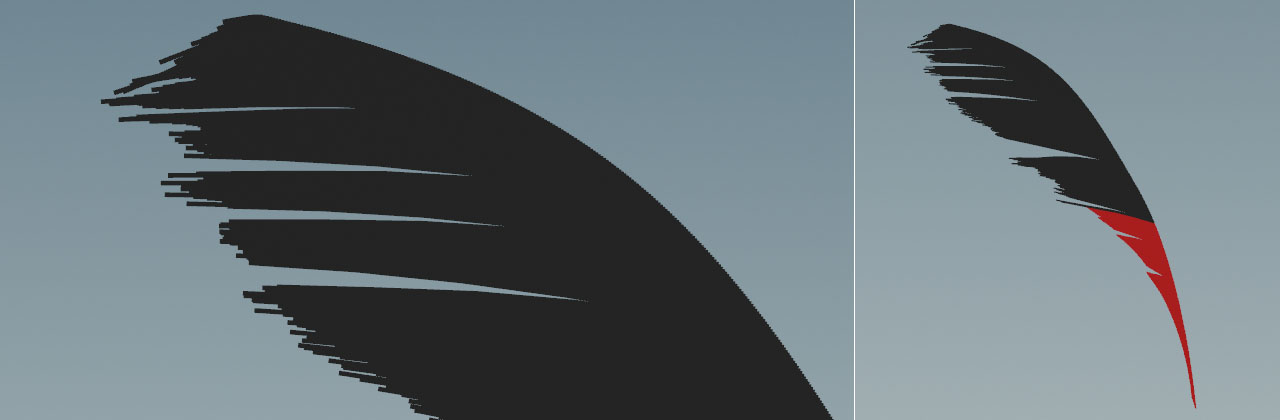
Left barbs: frizz 
When you take another look at the feather’s lower part, you can see some very long and fluffy barbs. However, the majority of barbs is short and even. The long barbs show a kind of gradient with shorter barbs near the bottom. The idea is to introduce an Attribute Wrangle to create a condition that selects a customizable number of barbs. These barbs are stored inside a frizzbarbs group.
Frizzbarbs group 
-
Add a new Primitive Wrangle SOP and rename it to
frizzgroup_left. -
Connect its first input with the first output of
setlength_left1. -
Go to Group and enter
lowerbarbs. -
On the VEXpression field, enter this code:
// Create the 'Number of Barbs' parameter
int num_of_barbs = chi("number_of_barbs");

// If a barb is identified, add it to the frizzbarbs group
if (@indexleft % num_of_barbs == 0) {
    @group_frizzbarbs = 1;
}
-
Click the
icon to create the Number of Barbs parameter. When you enter 2, every second barb oflowerbarbsis added to thefrizzbarbsgroup. With3, every third barb, and so on.
Set frizzbarbs maximum lengths 
Another Attribute Wrangle creates a maxlength attribute that is the product of a custom Max Base Length parameter and a factor to scale the barbs.
-
Add one more Primitive Wrangle SOP and rename it to
maxlength_left. -
Connect its first input with the first output of
frizzgroup_left. -
On the Group parameter, enter
frizzbarbs. -
The VEXpression for this node is
//Create a custom 'Max Base Length' parameter
float base_length = chf("max_base_length");

// Use 'indexleft' and 'barblimit' to create a factor between 0.1 and 1
float factor = fit(@indexleft, 0, @barblimit, 0.1, 1);

// Create a 'maxlength' attribute
@maxlength = base_length * factor;
-
Click the
icon again to add the Max Base Length parameter. You can start with a small value around 0.03and fine-tune it later. Here you can see that the orangefrizzbarbsas a subgroup of the redlowerbarbs.

Apply maxlength 
Now you have everything to scale the barbs of the frizzbarbs group through the maxlength attribute.
-
Lay down another Guide Process (Set Length) SOP and rename to
setlength_left2. -
Connect its first input to the output of
maxlength_leftand the second input to the second output ofsetlength_left1. -
On the General section, go to Group and enter
frizzbarbs. -
Go to the Operations tab ad turn on Randomize.
-
Enter a value for Min Length, e.g.
0.02. -
Next to Max Length there’s dropdown menu. Change it from No Override to Guide Attribute.
-
For Max Length Attrib, enter
maxlength.
You can now use the maxlength_left wrangle’s Max Base Length parameter to adjust the barbs' length. For this example the value is 0.029.
Bending 
This step adds some random curvature to the frizzbarbs group to make them more look as in the reference image.
-
Add a Guide Process (Bend) SOP and rename it to
bend_left. -
Again, set Group to
frizzbarbs. -
From the Mode dropdown, choose Axis Constant.
-
The Axis vector is
0,1,0. -
Use the Angle slider to monitor your changes. A value around
25should work here. -
Do the same for Random Angle. In this example, the value is
38.

Frizz 
Now you can add irregularities to the barbs.
-
Add a Guide Process (Frizz) SOP and rename it to
frizz_left. -
As before, the Group entry is
frizzbarbs. -
Decrease Amplitude to avoid extreme results. Most probably you’ll need a very small value. Here it was
0.0022. -
With Frequency and Random Frequency you can “crumple” the barbs. Try a value of
50for both parameters. -
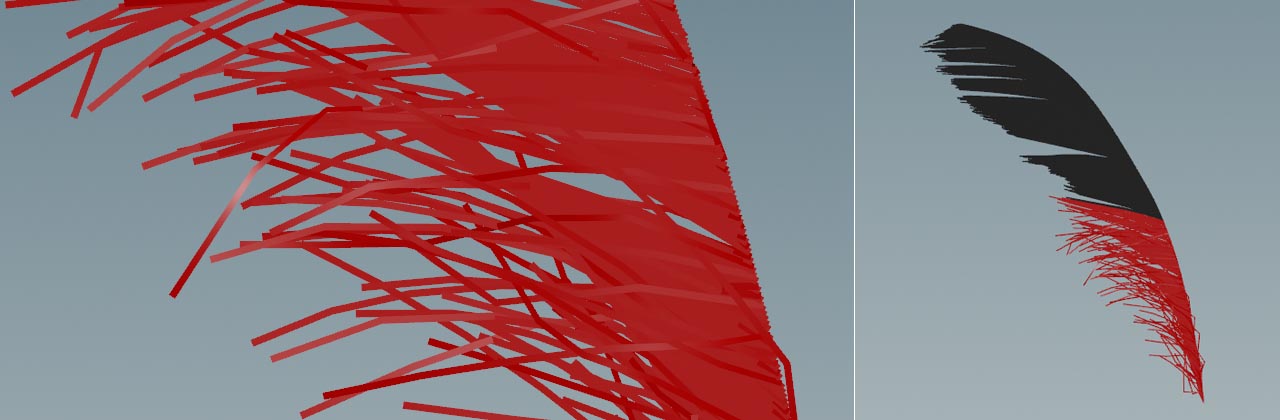
Finally, increase Random Amplitude to add more variation.
The result for the left barbs could look as in the image below.
Right barbs: notes 
Now you have to repeat the entire process for the right side of the feather. There, you can see that
-
there aren’t any frayed barbs near the tip, so you will only need one Guide Process (Set Length) SOP to randomize the barbs' lengths
-
the right part only has a few clumps
-
the barbs need a negative Angle on the Guide Process (Bend) SOP.
Here’s a view of the network for the barbs on the feather’s right side.
Merging 
Now you have three separated parts and it’s time to combine everything.
-
Add a
Merge SOP. -
Connect the first outputs of the
frizz_leftandfrizz_rightnodes to the Merge SOP’s input. -
Connect the output of the
shaftBlast SOP with the Merge SOP’s input.
Recreating the condensed state 
The condensed state of a feather is very resource-friendly, because it uses virtual barbs instead of curves. Houdini’s feather system provides a node to restore this state. This option will accelerate the grooming process, because you don’t have to deal with potentially hundreds of millions of points.
-
Connect its first input with the output of the Feather Template from Shape SOP.
-
Connect the fourth input with the output of the upstream Merge SOP.
-
Terminate the network with a
Null SOP. Rename the null to DOWNGEO(or any other name) and turn on its blue Display/Render flag.
Here’s the result of this workshop. In the next step you apply UVs and a texture. This process is described on the Feather texturing page.