| On this page |
Overview 
Often in rigid body simulations, you want a solid object to break into pieces because of some impact or force. For example, you might want an earthquake to destroy a house, with the concreate walls fracturing, the wood door splintering, and glass windows shattering. Or you might want a swinging demolition crane ball to cave in a wall.
-
Most fracturing tools in Houdini support a pre-fracturing workflow, where you break the geometry into pieces in SOPs, with the pieces held together by glue constraints. Pre-fracturing gives you full artistic control over the look of the destruction (for example, do you want big blocky pieces or small jagged pieces). The object will crumble when a force overcomes the glue strength, or you can manually animate the glue off when you want the object to break down.
The high-level tool for pre-fracturing geometry is the
 RBD Material Fracture SOP, with plenty of controls over different types of fracturing. There are many lower-level SOPs if you need even more control over fracturing.
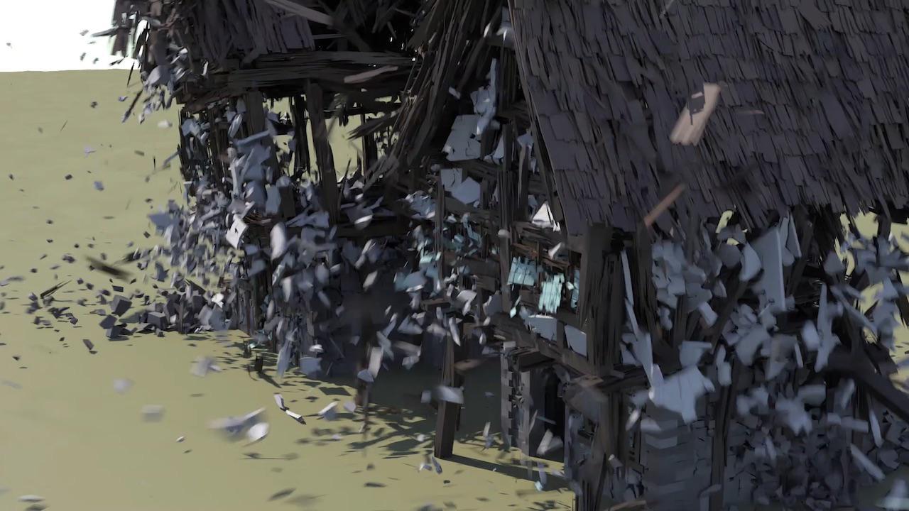
-
You can also do dynamic fracturing during the DOP simulation. See the help for
 Make Breakable tool for more information.
General workflow 
|
Simulates breaking patterns associated with different materials: concrete, wood, and glass.
|
-
Use the
RBD Material Fracture node to pre-fracture your model in SOPs. -
RBD Material Fracture automatically creates glue constraints between the fractured pieces. On the Constraints tab you can set the Primary strength to the initial glue strength you want.
After you import the fractured object into an RBD simulation (see the next step), you can go back and edit the settings on the RBD Material Fracture and edit the glue strength to control how much the pieces stick together.
The value depends on the size and weight of your pieces, and what effect you want to achieve. A value of
1will usually fall apart immediately.If you want the model to stay together until it’s hit by another RBD object, you will need to fine-tune the glue strength to a level where it’s high enough to keep the model stays together on its own, but not so high it prevents an impact from breaking the constraints.
-
Go up to the object level and select the fractured object. On the Rigid Bodies shelf tool, click the
 RBD Objects tool to import the object into DOPs as rigid body pieces.
See the rest of this page for more information on the available tools.
Tips 
-
Use the Group node to name groups of primitives. For example, the door, individual windows, and walls. This will allow you to fracture them individually.
-
If you see pieces spinning/wobbling in the simulation, you can particle drag to freeze them.
-
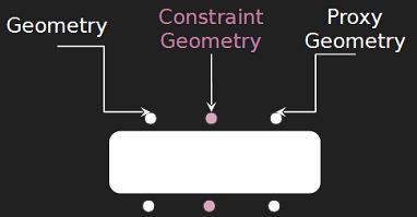
You can use the Output for view
 menu on RBD SOPs to choose which output is displayed. By default, the first output (Geometry) is displayed. However, you can also toggle between Constraint Geometry and Proxy Geometry.
 -
Clicking
 on outputs of the RBD SOPs will show the data for each individual output. Additionally, if you click on the inputs, it will trace up to the geometry data coming in.
RBD SOP inputs and outputs 
The RBD Material Fracture node and several other RBD SOP nodes share a consistent set of inputs and outputs, that let you send constraint geometry and proxy geometry through the network alongside the fractured geometry.
-
The first input/output is the high-resolution display geometry.
-
The second, colored input/output is constraint network geometry.
-
The third input/output is low-res proxy geometry.
Constraint networks 
The ![]() RBD Material Fracture tool not only fractures your geometry, but it also creates constraints for you between those pieces. If you want to create more constraints, there are 3 SOPs that allow you to do so, separate from the fracturing process. They follow the same 3 input/3 output RBD workflow, and give you a lot of control for building constraints. This is useful when you're fracturing two different types of materials, and want to create boundary constraints between them.
RBD Material Fracture tool not only fractures your geometry, but it also creates constraints for you between those pieces. If you want to create more constraints, there are 3 SOPs that allow you to do so, separate from the fracturing process. They follow the same 3 input/3 output RBD workflow, and give you a lot of control for building constraints. This is useful when you're fracturing two different types of materials, and want to create boundary constraints between them.
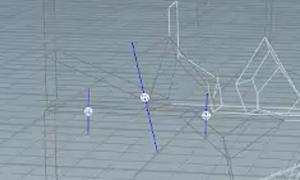
This tool is a very interactive way to build constraints, as you can simply click and draw constraints between the pieces you want to be connected in the viewport. Once the constraint is drawn, you can choose the Connection Type to determine how the constraints are set up. For more information, see the ![]() RBD Constraints From Lines help page.
RBD Constraints From Lines help page.
This tool lets you draw a curve in the viewport, and will create constraints between points on the geometry of nearby pieces within a specified search radius. RBD Constraints from Curves also gives you the option to provide a curve in the 4th input, so that you can use it procedurally. For more information, see the ![]() RBD Constraints From Curves help page.
RBD Constraints From Curves help page.
This tool is a procedural node for creating constraints based on a set of rules and conditions. For example, you can constrain pieces based on groups and then only constrain the pieces that are within a certain bounding region.
All three constraint nodes will create simple primitives with a rest length attribute. The ![]() RBD Constraint Properties SOP node can be used afterward to create constraint groups and set up constraint types (such as glue or soft constraints). The help for the
RBD Constraint Properties SOP node can be used afterward to create constraint groups and set up constraint types (such as glue or soft constraints). The help for the ![]() Constraint Network DOP has more background information about constraint networks (Constraint Network is the low-level DOP node responsible for converting SOP constraint geometry into the equivalent DOP constraints).
Constraint Network DOP has more background information about constraint networks (Constraint Network is the low-level DOP node responsible for converting SOP constraint geometry into the equivalent DOP constraints).
Types of connections 
All three constraint nodes (![]() RBD Constraints From Lines,
RBD Constraints From Lines, ![]() RBD Constraints From Curves, and
RBD Constraints From Curves, and ![]() RBD Constraints From Rules) will let you choose between the following types of connections.
RBD Constraints From Rules) will let you choose between the following types of connections.
|
The default connection that’s created is Hinges. These create a hinge-like constraint between pieces, which you can visualize by the white dot on the constraint line. |
|
Drawing Surface Points constraints will create anchor points where you clicked the mouse on the piece to place the constraint. |
|
Center of Mass constraints will calculate the center of mass for the constrained pieces and create constraints between their centroids. |
Understanding constraint networks 
Houdini lets you set up constraints in SOPs using constraint geometry. This is a set of polylines with attributes that represent constraint relationships between geometry pieces. These are translated into the equivalent DOP constraints when the geometry is imported into the DOP network. This is to make it easy to set up, edit, and visualize constraints using the large number of SOP nodes dedicated to editing geometry and attributes.
-
Each constraint is represented by a two-point polyline.
-
Each polyline has a
constraint_typeprimitive attribute specifying the constraint type. The two common RBD constraint types areglueandsoftconstraints.Glue constraints keep two pieces together until the amount of force trying to separate them is greater than the glue strength.
Soft constraints are similar to springs, but instead of being bouncy, they bend until they break.
-
The polyline can have additional primitive attributes related to the constraint, such as
strengthfor glue, orstiffnessanddampeningfor soft constraints. -
The two endpoints each have a
nameattribute specifying the name of the piece that end represents. -
The position of the endpoints may be used by different constraints, for example as anchor points.
Pre-constraining pieces 
If you have multiple connected pieces you want to fracture in different ways, you can optionally use the ![]() RBD Constraints From Rules node before you use
RBD Constraints From Rules node before you use ![]() RBD Material Fracture to break them up.
RBD Material Fracture to break them up.
For example, if you are destroying a house, you can start by constraining the door and windows to the walls they're embedded in.
As the RBD Material Fracture node breaks up the individual objects, it tries to intelligently update existing constraints. For example, if a pane of window glass starts constrained to the surrounding window frame, even as RBD Material Fracture shatters the glass, the node will keep the outer shards attached to the frame.
Low-res proxy geometry 
The RBD Material Fracture node can work on fast low-res proxy geometry. You need to set up high-res and low-res geometry with the same named pieces (for example, by breaking up the high-res geometry into named pieces and then copying and reducing the number of polygons to create the proxy).
Clustering 
Clustering refers to grouping fractured pieces into bigger clumps. There are two main clustering workflows:
-
If you just want a bunch of pieces to stick together permanently, give them all the same
nameattribute. Nodes that work on pieces will treat them as once piece.This can be useful, for example, with wood splintering, where you often want to group small splinters into bigger jagged chunks.
-
For certain directable crumbling effects, you will often want to work with bigger pieces early in the shot and have them break down into smaller pieces later in the shot. You can do this with a hierarchy of glue constraints. You can animate higher-level constraints off to break up bigger pieces into smaller pieces.
The RBD Material Fracture node provides clustering controls when the Material type is “Wood”. You can do manual clustering with the ![]() RBD Cluster node.
RBD Cluster node.
Importing a fractured object into DOPs 
The Rigid bodies shelf has tools for importing geometry objects into the DOP simulation.
|
Use this tool to import fractured objects. It automatically treats the named pieces as separate Bullet objects, and translates the constraint network geometry into Bullet constraints. |
Other rigid body simulation tools:
|
This is for importing an object as a single, unbreakable entity. Do not use this to import fractured geometry. |
|
|
This tool imports an object containing loose pieces and adds glue between them. Do not use this to import fractured geometry created with RBD Material Fracture since that node already creates glue constraints automatically. |
|
|
Sets up an object for dynamic fracturing in response to simulated impacts. |
|
|
Generates particles from the edges of crumbled pieces. You can use these particles to instance smoke, dust, pebbles, and so on as secondary effects. |
RBD SOP support nodes 
The following nodes work with the RBD Material Fracture node. They all have the same inputs and outputs as RBD Material Fracture.
|
Lets you paint attributes on the input geometry to control how the fracturing works, for example paint where you want more fracturing to occur.
|
|
|
Edits constraint geometry. This provides functionality similar to the parameters on the RBD Material Fracture node’s Constraints tab. You can use this as a convenient interface to edit values in the constraint network if you want to do more complex custom constraints. |
|
|
Adds noise to exposed interior surfaces after fracturing. This provides functionality similar to the parameters on the RBD Material Fracture node’s Detail tab. |
|
|
Groups pieces together into bigger pieces. This provides functionality similar to the parameters on the RBD Material Fracture node’s Cluster tab when Material type is “Wood”. |
|
|
Merges the three RBD SOP inputs (geometry, constraint network geometry, proxy geometry) into a single output. |
|
|
Splits out geometry, constraint geometry, and proxy geometry into separate RBD SOP-style outputs. |
|
|
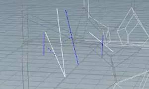
Creates rigid body constraint geometry from interactively drawn lines in the viewport. |
|
|
Creates rigid body constraint geometry from curves drawn in the viewport. |
|
|
Creates rigid body constraint geometry from a set of rules and conditions. |
Related SOPs 
The RBD Material Fracture node uses these lower-level nodes internally. You can use them separately if you want to.
|
Uses the |
|
|
Fractures geometry by creating cells from scattered points inside the geometry. |
|
|
Moves pieces away from each other (based on connectivity or |
Low-level SOPs 
These are lower-level nodes, many of which are used inside the RBD Material Fracture SOP to provide functionality. You may find them useful if you are doing complex custom fracturing.
|
Creates constraint geometry based on connectivity and proximity. This is a lower-level node providing functionality included in RBD Material Fracture. |
|
|
Assigns |
|
|
Very low-level node for Voronoi fracturing. |
|
|
Very low-level node for Voronoi fracturing. |