| On this page |
By default, the Vellum solver sources Vellum objects and constraints only on the start frame. Imagine, you want to emit water from a tap to fill a glass. In this case you need a continuous stream of particles that can be stopped at a certain frame. Another method is to trigger emission on attributes like position. You also might want to create particles from other sources like scatter points. The following chapters guide you through various emission and sourcing workflows.
Note
The methods, presented here, are also valid for Vellum grains.
The Emission Type parameter 
Emission methods are controlled through the ![]() Vellum Source DOP node. Depending on how you created your simulation network (DOP/shelf tools or SOP), the Vellum Source can be found in different places. The Emission Type parameter provides four options.
Vellum Source DOP node. Depending on how you created your simulation network (DOP/shelf tools or SOP), the Vellum Source can be found in different places. The Emission Type parameter provides four options.
-
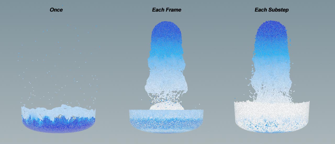
Only Once. Particles are only created at frame
1and then released from the source object. -
Each Frame New particles are created continuously during the entire frame range. This type can lead to gaps, especially with fast particles, because substeps aren’t considered.
-
Each Substep. Sourcing depends on the number of Substeps in the Vellum Solver and is performed during the entire frame range. For fluids,
10are a common value, and5for grains. Higher substeps create a more natural emission and more particles. Note that this type also increases simulation time and RAM usage. Anyway, avoid very high substeps of20or more, as they will make the fluid/grains more rigid: the solver’s Constraint Iterations are responsible for the fluid’s rigidity and applied per substep. -
Instance on Points. Like Each Frame, geometry is added every frame the DOP is active. However, a point geometry with attributes like
orientandNis created. Geometry and attributes can be used for instancing and match the Copy to Points SOP node’s behavior.
Emission Type in DOP networks 
In DOP-based networks, e.g. if you have created the setup through the ![]() Vellum Grains shelf tool, double-click the
Vellum Grains shelf tool, double-click the AutoDopNetwork node to open it. There, select the Vellum Source node. In the parameter pane, look for Emission Type.
Emission Type in SOP networks 
In SOP-based networks, the Vellum Source DOP is located deep inside the locked ![]() Vellum Solver SOP. To make the Vellum Source directly accessible, a few steps are required.
Vellum Solver SOP. To make the Vellum Source directly accessible, a few steps are required.
-
If the Vellum Solver’s first two inputs are linked to another node, cut the connections. In the Network Editor, press and hold the Y key. The cursor turns into a pair of scissors and you can cut the links.
-
Press ⇥ Tab to invoke the TAB menu and enter
null. Create two Null SOP nodes.
 -
Rename one Null to
GEOand connect it to the Vellum Configure Grain SOP node’s first output (Geometry).
 -
Rename the other Null to
CONand connect it to theVellum Configure Grain SOP node’s second output (Constraints). -
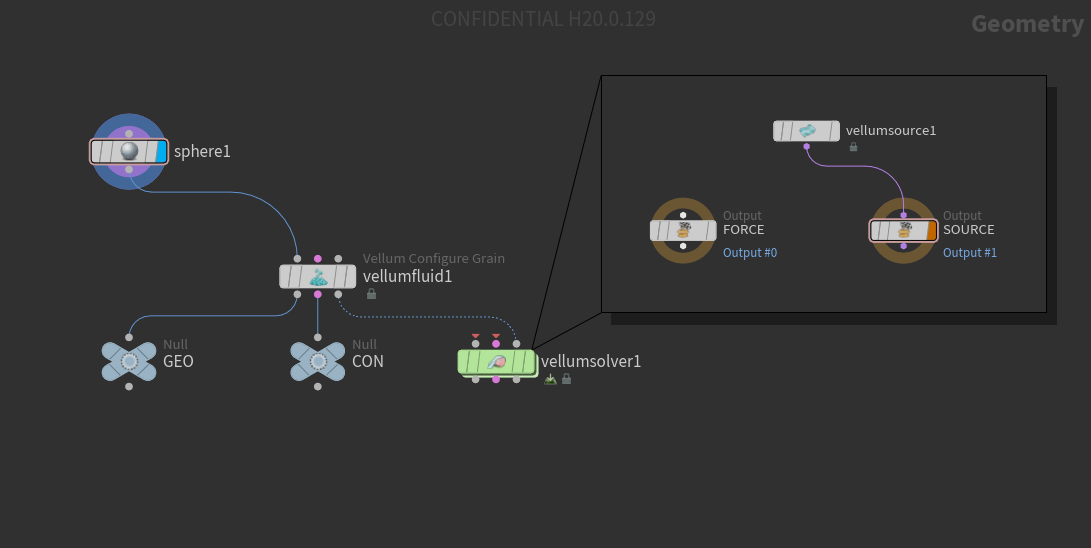
Double click the Vellum Solver to dive into it.
-
Add a Vellum Source node and connect it to the
SOURCEOutput DOP’s input. -
In the Vellum Source, go to Source ▸ SOP Path and click the
 icon to open the floating operator choose. In the chooser, look for the
 GEOnode and Accept it. -
Do the same for Source ▸ Constraint SOP Path, but this time choose the
CONnode. -
The Vellum Source node now provides direct access to the Emission Type parameter.
If you go back to geo1 level, you can see that the first two solver inputs are still empty, although they're mandatory. If you connect the Vellum Configure outputs to the solver, you add two sources and double the number of particles. To create the correct number of particles, only one method can be used: either solver inputs or the Vellum Source DOP.
This is how a basic setup should look:
Controlling emission through expressions 
All emission types start at frame 1. Only Once stops immediately, the other types stop at the simulation’s end frame. You can control sourcing by animating the Vellum Source node’s Activation parameter through animation keys or expressions. Here, the expressions work like switch to turn Activation on (1) or off (0). Parameters with HScript expressions are displayed in green, with Python they're purple. Below you find some common sourcing tasks and their corresponding expressions.
| To... | Do this |
|---|---|
|
Limit sourcing to a certain frame |
|
|
Start sourcing at a certain frame |
|
|
Stop sourcing at a certain frame |
|
|
Limit sourcing to a certain frame range |
|
|
Limit sourcing to multiple frame ranges with Python |
Parameter expressions can also be written in Python instead of HScript. Here, sourcing should be limited between frame
activate = 0

if (frame() > 4 and frame() < 11):
    activate = 1

elif (frame() > 20 and frame() < 25):
    activate = 1

return activate
Houdini’s internal name for the Activation parameter is |
|
Trigger sourcing through relative references |
You can start sourcing through references, e.g. when an animated object reaches a certain position. Imagine a box that is animated along the X axis. Once the box reaches X = 2, Activation should be set to
|
|
Use animation keys to define sourcing ranges |
Another way is to animate Activation.
|
Point source emission 
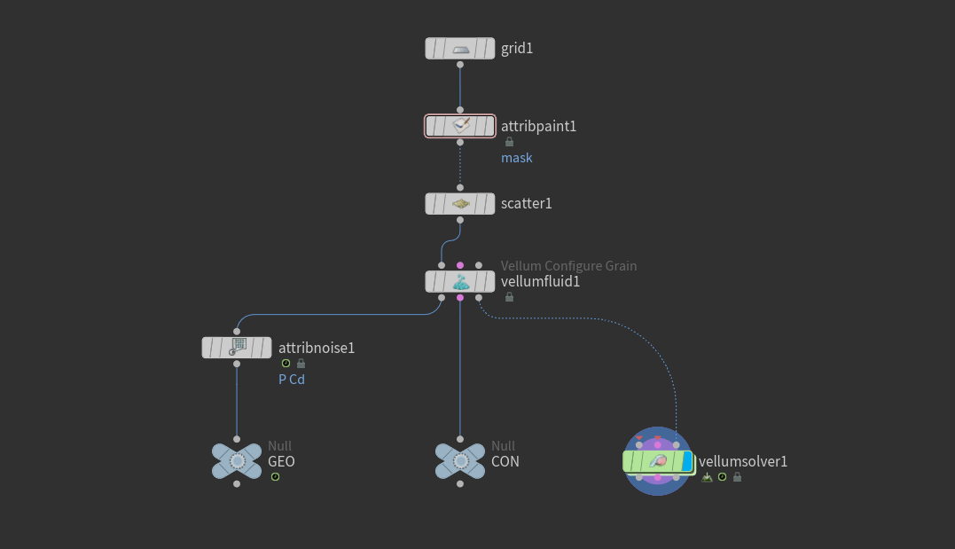
Particles can be created from volumes, but also from other point sources. Point sources can be, for example, scatter points, but also points on a curve. Point sources in conjunction with masks or images let you precisely define, where particles should be sourced or spared out. The following setup uses a ![]() Grid SOP with a painted mask and scattered points to create a custom particle emitter. Here’s a screenshot of the entire network for reference:
Grid SOP with a painted mask and scattered points to create a custom particle emitter. Here’s a screenshot of the entire network for reference:
-
On obj level, press ⇥ Tab to invoke the TAB menu. Enter
geoto create a Geometry SOP node.
 -
Double click the node to dive into it.
-
Add a Grid SOP and set its Size to
5 x 5. -
Change Center.Y to
2and Rotate.X to30. -
Increase Rows and Columns to
200. This is necessary to draw a smooth mask.
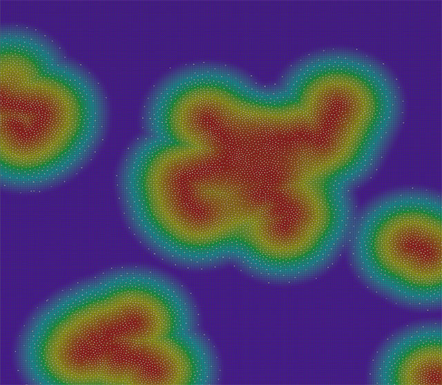
The mask can be painted directly onto the grid.
-
Add an
 Attribute Paint SOP node and connect its input to the Grid’s output.
 -
Select the new node and turn on its Display/Render flag. You should already be in drawing mode: the grid is purple and you can see a 3D brush.
-
To scale the brush, use the
 .
. -
In the Attribute Paint node’s parameters, set Soft Edge to
1. -
Draw a mask to your likeness.
Create the particles in the masked areas.
-
Add a
 Scatter SOP and connect it to the upstream Attribute Paint node.
 -
Set Force Total Count to
8000. -
Turn on Density Attribute and replace the default entry by
mask. The scatter points should only appear in the masked area.
Fluid setup 
In this example you create a SOP-based fluid setup. Visit the Vellum fluid setups page for more information on differences between DOP and SOP networks.
-
Add a
Vellum Configure Fluid node. You can see from the node description that this is actually a Vellum Configure Grain node. Link its first input to the Scatter node’s output. -
Turn off Create Points from Volume.
-
For Particle Size choose a value that is small enough to separate the particles. In this example, use
0.035.
Note
In the next step, the particles' geometry and constraints have to be connected to the ![]() Vellum Solver SOP. For SOP networks, you need a certain setup to get access to a
Vellum Solver SOP. For SOP networks, you need a certain setup to get access to a ![]() Vellum Source DOP. This node provides the Emission Type parameter and lets you choose, whether you want to source particles once, each frame or each substep. For a setup guide, please return to the 'SOP networks' chapter above.
Vellum Source DOP. This node provides the Emission Type parameter and lets you choose, whether you want to source particles once, each frame or each substep. For a setup guide, please return to the 'SOP networks' chapter above.
-
Keep the Vellum Source node selected.
-
Set Emission Type to Each Frame.
-
Turn on Ground Position to create an infinite ground collision object.
-
Return to geo1 level.
The scene is ready to simulate. To get rid of the uniform look, follow the steps below.
-
Add an
 Attribute Noise SOP node and place it between Vellum Configure and the
 GEONull. -
Under Attribute Names, append
Pfor position.Cdstands forcolorand can be kept if you want differently colored particles. The attributes have to be separated through a blank. -
For Amplitude, enter
1.5to achieve a stronger displacement. -
Expand the Animation subpane and turn on Animate Noise.
-
Press the
 button to start the simulation.
The video below shows how the simulation could look.
Emission from polygon selections 
Instead of paining a mask you can also restrict particle sourcing to selected polygons, not the entire object. To do this, you have group the polygons you want to use for emission, for example with the help of a ![]() Group Expression SOP. This node has to be placed directly after the polygon object you want to use as a particle source. You can use the previous setup (see network screenshot above) with a few modifications.
Group Expression SOP. This node has to be placed directly after the polygon object you want to use as a particle source. You can use the previous setup (see network screenshot above) with a few modifications.
-
Replace the Grid SOP through another object, e.g. the
 Rubber Toy SOP.
 -
Delete the Attribute Paint and Attribute Noise SOPs.
-
Select
scatter1and turn off Density Attribute, because it’s no longer needed here.
These are the nodes and settings to create a particle selection.
-
Add the Group Expression SOP from the TAB menu and place it between Rubber Toy and Scatter.
-
Make sure that Group Type is set to Primitives.
-
Go to Group Name and enter a name, e.g.
emission. -
Under VEXpression enter an expression like
fit01(@elemnum % 10 * @N.y,0,1). This expression selects polygons based on the normals' Y components. The factor10can be modified to select more or less polygons. Note that the factor must be an integer. Of course you can also manually select polygons or use other methods. -
In the Scatter SOP, go to Group and enter
emission.
Note
It might happen that the particles disappear when you select the solver or start the simulation. In this case, go to vellumfluid1 and decrease Particle Size until the particle reappear.
How to 
| To... | Do this |
|---|---|
|
Avoid gaps between particles |
Alternatively, you can also add a drag force to slow down the particles. You have to distinguish between DOP and SOP networks.
|
|
Avoid regular emission patterns |
|