| On this page |
With phases, Vellum will solve for viscosity and surface tension separately to simulate different types of fluids. This option is only available for fluids and you can’t combine grains and water through phases, for example. You're also not limited to two phases. You can find the parameter in the ![]() Vellum Constraints Grain SOP node’s Physical Attributes subpane. Note that Type has to be set to Fluid. It is, of course, possible to set up two fluids and ignore phases, but the results might not meet your expectations. Fluids with
Vellum Constraints Grain SOP node’s Physical Attributes subpane. Note that Type has to be set to Fluid. It is, of course, possible to set up two fluids and ignore phases, but the results might not meet your expectations. Fluids with
-
equal Phase values, but different Viscosity and/or Surface Tension settings often stick together in touching areas
-
different Phase values, but no Viscosity difference will interact, but behave like two fluids with no friction between them
-
different Phase values, and Viscosity and/or Surface Tension will separate more and hardly stick together.
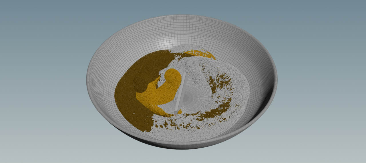
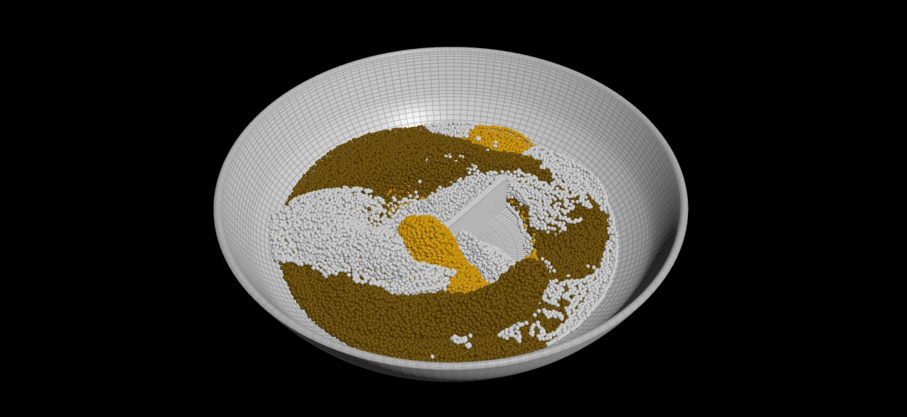
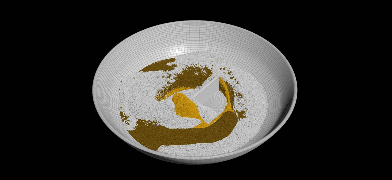
In the following example you create a scene with three fluids, pouring into a bowl: the first fluid behaves similar to slightly whipped cream, the second one is liquid chocolate, and the third liquid is comparable to caramel. To make everything more interesting, a blender stirs the ingredients. Note, that the fluids don’t have to be physically correct. The project’s main purpose is to demonstrate the concept and show, how various substances interact. You can therefore use other parameter combinations.
The project is subdivided into several main parts:
-
The bowl’s geometry
-
Source objects
-
Creation of a fluid network template
-
Solver settings
-
Connecting fluids and solver
Note
At the end of this page you can find two files available for download. The first file contains only the bowl and blender objects; the second file is the complete project for reference. The following descriptions are all based on the first file’s nodes.
Bowl and blender 
The bowl is an object of revolution and acts as a collision object for the fluids.
-
Load the file and double click the
fluid Geometry SOP node to dive into it.
 -
There, you can see five nodes, describing the bowl’s shape.
-
The blender is just a
 Box SOP.
 -
Click the Box node and go to Rotate.Y. There, enter
$FF*15. This expression makes the object spin around its Y axis.$FFstands for the exact frame and the value is multiplied with a factor of15. By changing the factor, you can make the blender slower or faster.
Source objects 
The fluid sources are three identical spheres, rotating around the bowls' center. Instead of keyframing the spheres' positions, you can use expressions. This makes it much easier to apply changes to rotation speed, start position, and radius.
-
Add a
 Sphere SOP.
 -
Set Uniform Scale parameter to
0.1. -
Change Center.Y to
0.2 -
Use ⌃ Ctrl + C and ⌃ Ctrl + V twice to copy and paste the Sphere node. You now have three spheres.
-
Rename the objects to
source_cream,source_chocolate, andsource_caramel.
Motion expressions 
A circular motion can be described through sine and cosine functions. The parametric formulas for this scene are sin($FF*speed+offset)*distance and cos($FF*speed+offset)*distance
-
speedis a factor and higher values make the sphere faster. -
offsetshifts the sphere’s starting position. -
distanceis the distance to the scene’s midpoint and measured in meters.
Add the sine function to a sphere’s Center.X, the cosine function to Center.Z. Together, the expressions describe a circle with a clockwise motion. For a counterclockwise motion, one of the expressions has to start with a - (negative) sign. For
-
source_creamusesin/cos($FF*7+160)*0.2 -
source_chocolateusesin/cos($FF*6)*0.3 -
source_caramelusesin/cos($FF*4+100)*0.1.
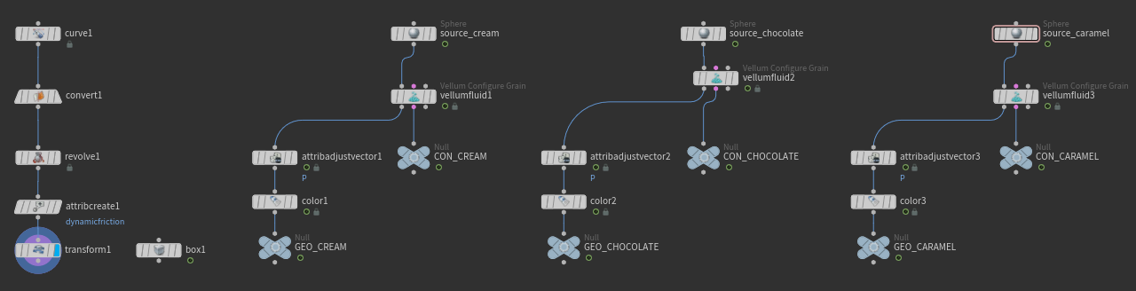
Fluid template 
The scene contains three different types of fluid and each material has to be defined separately. A fast way is to create a network for the first fluid, copy/paste it, and make the individual settings.
-
From the TAB menu, add a
 Vellum Configure Fluid SOP. When you look at the node, you can see that this element is a Vellum Configure Grain SOP, but preconfigured for fluids.
 -
For testing, Particle Size can be rather large. Enter a value of
0.01. In the final simulation, this parameter will be decreased to0.005. This value creates a final particle count of roughly 530,000. A sufficient number of particles is essential if you want to create fine structures and drops. -
The parameters in the Physical Attributes subpane define, which type of fluid you want to create. The settings will made later.
Even with relatively large Particle Size values you get a good approximation of the final simulation. Drag the slider to compare the images:
The following attribute and color nodes are not absolutely necessary, but help to add more randomness and separate the fluids visually.
-
Add an
 Attribute Adjust Vector SOP. This node will add some position randomness to the particles to avoid an uniform look.
 -
Link its input to the first output of the Vellum Configure Grain node.
-
Go to Attribute Name and delete the
ventry. Then typePfor position. -
From the Adjust with dropdown menu, choose Noise.
-
From the Range Values dropdown menu, choose Min/Max.
-
Set Min Value to
-0.02and Max Value to0.02. These settings displace the particles randomly at creation time. -
Open the Animation subpane and turn on Animate Noise.
-
Add a
 Color SOP and connect it to the Attribute Adjust Vector node’s output.
 -
Add two
 Null SOPs.
 -
Connect one Null to the Color SOP’s output. The Null terminates the chain and stores the particles.
-
Connect the other Null to the Vellum Configure Grain node’s second output to store the constraints.
Now, use the ![]() to draw a rectangle around the template nodes (Vellum Configure Grain, Attribute Adjust Vector, Color, Nulls) and select them.
to draw a rectangle around the template nodes (Vellum Configure Grain, Attribute Adjust Vector, Color, Nulls) and select them.
-
Press ⌃ Ctrl + C to copy the nodes, and two times ⌃ Ctrl + V to paste them.
-
Go to the Color SOP. Choose a brownish Color for chocolate and orange for caramel.
-
Rearrange the networks to separate them.
You now have three networks for cream, chocolate and caramel.
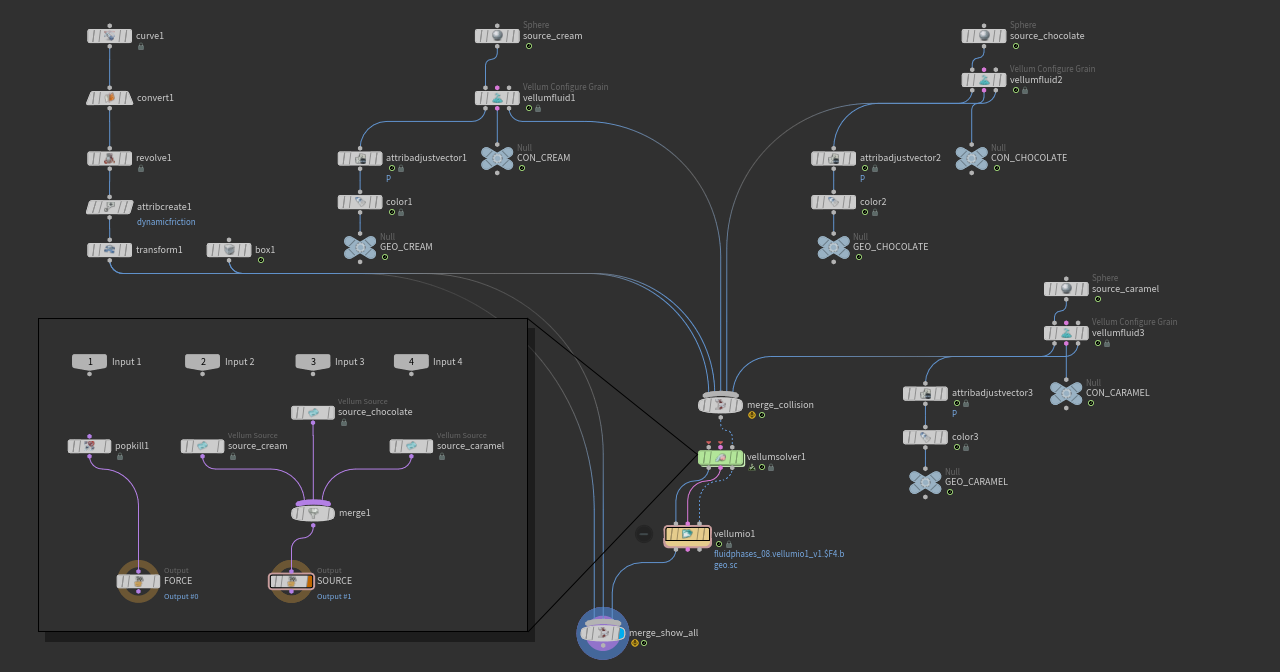
Connections and node names 
Connect the first inputs of the Vellum Configure Grain nodes with the outputs of their corresponding source spheres: source_cream, source_chocolate, and source_caramel.
To make the different networks distinguishable, apply names for the Nulls:
-
The Nulls that are connected to the Color SOP should be named
GEO_CREAM,GEO_CHOCOLATE, andGEO_CARAMEL. -
The Nulls that are connected to the Vellum Configure Grain nodes' second output should be named
CON_CREAM,CON_CHOCOLATE, andCON_CARAMEL.
Your network setup should now look like this:
Fluid settings 
The first network simulates slightly whipped cream.
-
Click the first Vellum Configure Grain node (connected to
source_cream) to open its parameters. -
Expand the Physical Attributes subpane.
-
For Density enter
1100. This is slightly more than the density of water. -
Check, if Phase is set to
1. This parameter tells the solver that you want to use fluids with different physical settings and cares for better particle separation. -
Turn on Viscosity and enter a value of
50. -
Turn on Surface Tension and enter a value of
40.
Use the following settings for chocolate:
-
Set Density to
1300. -
Change Phase to
2. -
Turn on Viscosity and enter a value of
250. -
Turn on Surface Tension and enter a value of
10.
Here are the values for caramel:
-
Increase Density to
1600. -
Change Phase to
3. -
Turn on Viscosity and enter a value of
2000. -
Turn on Surface Tension and enter a value of
5.
Collision 
The Vellum Configure Grain nodes provide a third output: Collisions. The particles should also interact with the bowl and the rotating blender.
-
From the TAB menu, add a
 Merge SOP.
 -
Connect the bowl’s Transform and Box outputs with the Merge node.
-
Connect the third outputs of the Vellum Configure Grain nodes with the Merge node. Merge should now have five incoming connections. Later, the Merge SOP is linked to the solver to establish the connection.
-
By default, the collision geometry is visible. If you want to hide the collision geometry, go to the Vellum Solver’s Visualize tab, and urn off Show Collision.
Solver settings 
The ![]() Vellum Solver SOP is the network’s centerpiece. It processes the incoming information from the
Vellum Solver SOP is the network’s centerpiece. It processes the incoming information from the GEO and CON nodes, and the collision objects.
-
Add a Vellum Solver SOP and connect its third input (Collisions) with the Merge node’s output. Although the first two inputs are mandatory, they will remain empty here. The connection between particle geometry, constraints and solver is done a little later inside the Vellum Solver through the
GEOandCONNulls. -
Go the Solver tab and change Substeps to
7. The recommended minimum value for fluids is5, but in simulations with high viscosity, Substeps should be higher to stabilize the particles. -
For fluids, Constraint Iterations should be around
20. -
Smoothing Iterations aren’t needed here and can be set to
0.
To establish the particle-constraint-solver connection, additional nodes have to be introduced. Double click the solver to dive into it.
-
From the TAB menu, add a
 Vellum Source DOP and a Merge node.
 -
Connect Vellum Source and Merge; then link the Merge node’s output with the input of
SOURCE. -
Click the Vellum Source to open its parameters.
-
Click the SOP Path parameter’s
 operator chooser. From the node tree choose
 GEO_CREAM. -
Do the same for Constraint SOP Path, but choose
CON_CREAM. -
Change Emission Type to Each Substep. This parameter is not directly accessible in Vellum SOP networks, but necessary. Therefore, the particle-constraint connection can’t be established through the solver’s inputs. Without Emission Type, fluid is only sourced at frame 1.
Connections are also required for the chocolate and caramel networks.
-
Press ⌃ Ctrl + C to copy the Vellum Source, and ⌃ Ctrl + V to create two copies.
-
Connect the copies to the Merge node.
-
Change the SOP parameters of the first copy to
/obj/fluid/GEO_CHOCOLATEand/obj/fluid/CON_CHOCOLATE. -
The entries for the second copy are
/obj/fluid/GEO_CARAMELand/obj/fluid/CON_CARAMEL.
Activating the sources 
By default, particle sourcing starts at frame 1 for all three fluids. However, the simulation looks more interesting with different start and stop frames. Expressions are a fast way to animate the Activation parameter and control sourcing.
Note
If you want to learn more about how to control sourcing, please read the Emission methods page. There you can find many examples and setups.
-
The Vellum Source for cream should create particles between frame
42and120. Go to the Activation parameter and enterif($FF>42 && $FF<120,1,0). This expression switches the parameter from0to1in the specified frame range. -
For the chocolate source, use
$FF<131. Here, sourcing starts a frame1and ends at130. -
The caramel source’s expression is
if($FF>24 && $FF<122,1,0). -
Return to fluid level.
Deleting stray particles 
Some particles are highly accelerated and leave the bowl. You can remove stray particles with a ![]() POP Kill DOP inside the Vellum Solver.
POP Kill DOP inside the Vellum Solver.
-
Double click the Vellum Solver to dive into it.
-
From the TAB menu, add a POP Kill DOP and connect it to the
FORCEnode. -
In the Rule tab, turn on Enable to make the VEXpression field editable.
-
Type the following expression:
if (length(@v) > 1.7) {
    dead = 1;
}
This short expression calculates the length (= speed) from the velocity vector v for each particle and compares it against a threshold. When a particle’s speed is greater than 1.7, the condition is fulfilled and the particle removed. The threshold is the result of several test simulations.
Friction 
To make the fluids stick on the bowl’s surface, you can add friction. Vellum provides two methods: per-particle friction and object friction. When you take a look at the vellumfluid1 node’s parameters, you can see Friction and Dynamic Friction. The parameters are multiplied with the corresponding Vellum Solver’s Static Threshold and Dynamic Scale. In this scene, object-based friction is used.
-
Add an
 Attribute Create SOP.
 -
Place the new node between Revolve and Transform to connect them.
-
The attribute’s Name is
dynamicfriction. -
Make sure that Class is set to Point, because with friction, Vellum interprets geometry also as points.
-
Go to the first Value field and enter
4.
Caching 
The scene takes a while to simulate and the results should be saved to disk. Vellum provides a dedicated node to cache geometry, constraints, and collisions in one pass.
-
On fluid level, add a
 Vellum I/O SOP and connect its inputs to the three corresponding Vellum Solver outputs.
 -
You can go on with the I/O node’s default settings and click Save to Disk or Save to Disk in Background. The difference between both methods is that Houdini’s UI remains responsive with the latter method.
Here is the complete network setup:
You are now ready to start the simulation. Go to the playbar and press the ![]() button. If everything works as expected, the result should be similar to the video below. You can see that the particles are sourced at different positions and times. Friction makes the fluids stick to the bowl’s surface, creating a more natural look. Cream, the fluid with the lowest Density, floats on top of the chocolate and caramel. The video below shows the simulation with Particle Size set to
button. If everything works as expected, the result should be similar to the video below. You can see that the particles are sourced at different positions and times. Friction makes the fluids stick to the bowl’s surface, creating a more natural look. Cream, the fluid with the lowest Density, floats on top of the chocolate and caramel. The video below shows the simulation with Particle Size set to 0.002.
In this clip, all Phase parameters are 1. The fluid mixes more and most surface structures have vanished. Especially the white cream particles behave completely different.
Files 
This example contains the necessary objects to create interacting Vellum fluids with different Viscosity and Surface Tension settings through the Phase parameter.
This example contains is a complete setup for creating interacting Vellum fluids with different Viscosity and Surface Tension settings through the Phase parameter.