Houdini 20.0 Vellum

Surfacing Vellum fluids

On this page

Overview

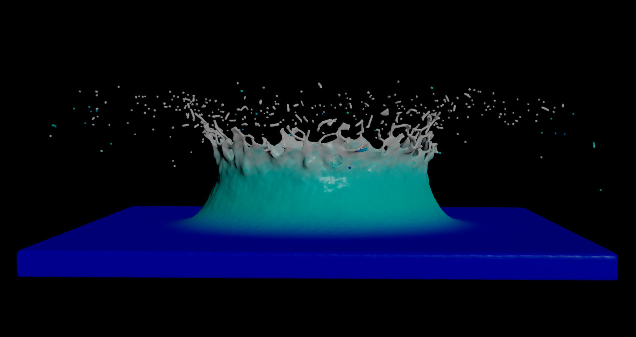
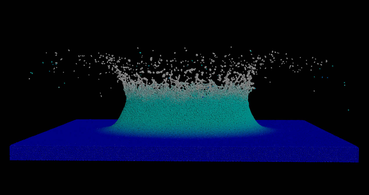
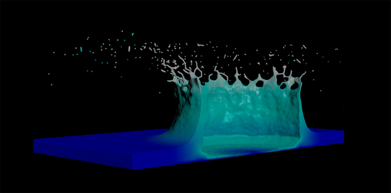
Vellum fluids use particles to simulate a fluid’s behaviour and shape. In order to render the fluid as a solid object you have to turn the particles into a polygon mesh. This process is called surfacing and requires a Particle Fluid Surface SOP node. Plug the particles' geometry to the node’s first input. Surfacing also means to find a good balance between the fluid’s level of detail and the number of polygons to catch as many structures as possible.

Tip

The Particle Fluid Surface SOP can also be used with Vellum grains and FLIP fluid particles.

How to

To...Do this

Quick start

  1. Go to a frame that contains as many details as possible.

  2. Change Method to Average Position. The preadjusted Spherical mode might be slow.

  3. Start with Particle Separation. The value should be at least the same as the Vellum Configure Grains SOP node’s Particle Size. Smaller values create more details, but also more polygons.

  4. A moderate increase of Influence Scale may help to smooth the surface and close smaller holes. The same applies to Droplet Scale.

  5. Instead of playing with Influence Scale and Droplet Scale consider filtering. Filters like Dilate or Smooth also help to improve mesh quality, but they are faster and less memory-intensive.

Use Voxel Scale

  • The default Voxel Scale value gives good results in many situations.

  • The value will be multiplied with Particle Separation to define a VDB voxel’s edge length.

  • For example, with Particle Separation set to 0.015 and a Voxel Scale of 0.5, the edge length will be 0.0075.

Compare the surface with the particle simulation

  1. Turn on the Particle Fluid Surface SOP’s Display/Render tag to visualize the surface.

  2. Turn on the Template tag of the node that is connected to the Particle Fluid Surface SOP’s first input.

Avoid a muddy or blobby look of the surface mesh

  • Increase the number of particles by decreasing the Vellum Configure Grains SOP node’s Particle Size.

  • Use the Particle Fluid Surface SOP node’s Dilate filter.

  • Moderately decrease the Particle Fluid Surface SOP’s Influence Scale and Droplet Scale values.

Improve surface quality

  • The more particles, the better the surface mesh will turn out. Decrease the Vellum Configure Grains SOP’s Particle Size value to get more particles.

  • Decrease the Particle Fluid Surface SOP’s Particle Separation to get more details.

  • The same applies to the number of polygons, because more polygons help to represent smaller structures like droplets or thin tendrils.

  • The Vellum Configure Grains SOP’s Packing Density helps to get a better representation of the sourcing object. Note that this attribute should only be used with Vellum fluids.

  • Filters are a good and fast way to fine-tune the surface.

Include attributes

Some attributes are transferred to the surface by default, for example velocity (v) and vorticity. Custom attributes can be added as well:

  1. Create the attribute, for example through an Attribute Wrangle SOP node.

  2. Make sure that the node that creates the attribute is placed before the Particle Surface Fluid SOP.

  3. Go to the Particle Surface Fluid SOP’s Transfer Attributes and append the previously created attribute to the list.

  4. Use Attribute Radius and Attribute Samples to smooth the attribute values. This is often necessary to enhance motion blur quality.

Display the velocity attribute

  1. In the Particle Fluid Surface SOP, go to Surfacing ▸ Output and make sure that Transfer Attributes is turned on. Look for the v entry.

  2. From Visualize select Velocity.

  3. Adjust Velocity Range to get the full color spectrum from the Velocity Ramp.

Subtract geometry from the surface

You can optionally subtract geometry from the generated surface before it is converted to polygons. For example, you can prevent the node from generating polygons outside the fluid’s container object, or within objects the fluid is colliding with.

  1. Connect the volumes/geometry you want to subtract from the surface to this node’s second input (“Collision objects and volumes”).

  2. In the parameter editor, click the Regions tab and turn on Subtract collision volumes.

Vellum

Cloth

Softbody

Fluid

Constraints

Collisions

Other

Advanced