| On this page |
The new shape matching matching method in Houdini 19.5 allows for the simulation of rigid objects in Vellum. The idea is to use an object’s volume and pack it with spheres to match the original shape as close as possible. Constraints keep the spheres together and create a structure that behaves very similar to a rigid body. Collisions between spheres and other objects are very fast to calculate and the method is also suited for large object counts.
Shape matching is based on Vellum grains. A new Sphere Packing method provides parameters to fill an object with spheres. The spheres can have uniform sizes or variable sizes to catch smaller object structures. The spheres can also overlap to get a better representation of the object. Anyway, spheres can only be an approximation and with complex geometry, it is likely that you will see intersections between the simulation objects. You can improve collision with more spheres, but this will slow down the simulation.
Note
Shape match simulations require the latest driver for NVIDIA Ampere (or later) cards. Older chipset architectures aren’t supported. If you experience problems, go to Houdini’s main menu. There, open Edit ▸ Preferences ▸ Miscellaneous and set OpenCL Device to CPU. Then, restart Houdini to apply the changes.
Preparing the geometry 
The following setup illustrates the basic functionality of Houdini’s new shape matching technology. Start with the object you want to turn into a rigid body.
-
On obj level, create a
 Geometry node and dive into it by double-clicking it. This node will serve as a container for the network setup.
 -
Inside the Geometry node, press ⇥ Tab to access the node menu. Enter
rubberand choose Test Geometry: Rubber Toy.
 -
Under Translate, set the Y value to
2to move the object above the (imaginary) ground. -
For Rotate, add random values, e.g.
60,40,70to get a more interesting result. -
Add a Copy and Transform node and connect it with the rubber toy. This node creates a custom number of copies from the original object. For now, go on with a single object and set Total Number to
1. -
Turn on Pack and Instance to group the toy’s individual parts. Without this option, the flippers will separate from the toy’s body and the object falls apart.
Note
If you use several Copy and Transform nodes to create object arrays, please make sure that only the first node has Pack and Instancing turned on.
Sphere packing 
The sphere packing method is based on grains and has to be configured for the rubber toy object.
-
Add a
 Vellum Configure Grain node and connect its first input with the
 copy1node’s output. -
Turn on Create Points from Volume to fill the rubber toy with sphere. When turned on, the toy disappears from the viewport and you only see spheres, representing the object’s volume. You can make the toy visible again in a later step.
-
Set Method to Sphere Packing. This option changes the look of the spheres and you can see several more parameters. These parameters are used to control the spheres' sizes and number.
-
With Particle Size you determine the object’s resolution and the quality of the interaction. Smaller values create more spheres, but will also require more memory.
-
A good idea is to turn on the Overlapping checkbox, and check, if you can get a better representation of the base object.
-
Now, turn on Max Radius Scale. This action normally creates spheres of different size and reduces the number of packing spheres. Enter
3to optimize the packing process. -
Turn on Define Pieces and then Transfer Piece Attribute. This action makes the copies and instances distinguishable. Right now, there is only one copy and the
pieceattribute’s only value is0, but for multiple copies, the attribute serves as an id. You can check thepieceattribute’s value in the Geometry Spreadsheet
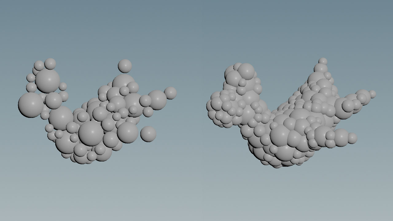
The image shows the rubber toy’s sphere representation with Overlapping turned off (left) and on (right).
Constraints 
The packing spheres have to be connected through constraints to achieve the desired behavior. This is done with the following node.
-
Lay down a
 Vellum Constraints and wire all three inputs to the upstream Vellum Configure Grain operator’s outputs.
 -
From the Constraint Type menu, choose Shape Match. This option tells the solver to do everything to maintain the original shape and create a quasi-rigid-body constraint setup. Take a look at the Stretch section. There you can see that the Stiffness multiplier is set to an extremely high value of
1e+10to make the constraints rigid. -
Set Group Type to Points to establish constraints between the grains.
-
Go to the Define Pieces menu, and choose From Attribute.
-
Under Piece Attrib, delete
classand enterpiece. -
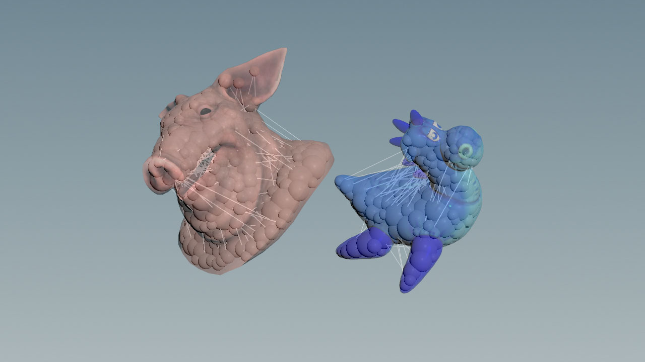
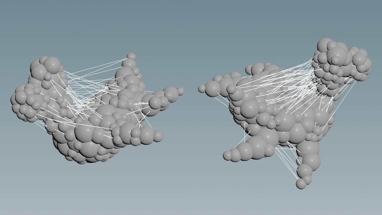
Turn on the node’s Render/Display flag to see the constraints. The setup should look similar to the image below.
Solver settings 
The next node processes the input data and performs the simulation.
-
Add a
 Vellum Solver and connect its three inputs with the Vellum Constraint’s three outputs.
 -
In the Solver tab’s Collision sub-pane, turn on Ground Position to create a ground collision object.
-
If you had to set Houdini’s OpenCL Device to CPU (see note above), go to Advanced ▸ OpenCL and check, if OpenCL Neighbor Search is turned off or inactive. If this option is on, the object won’t move.
Transfer simulation data to the object 
The last node transfers the simulation data from the packed spheres to the rubber toy object.
-
Add a
 Vellum Transform Pieces node.
 -
Connect the first two inputs with the solver’s first two outputs.
-
Connect the 3rd output with the
copy1node’s output. -
Go to Piece Attribute and check, if it contains
piece. If not, enterpiece.
The network is ready. Click ![]() to start the simulation.
to start the simulation.
Note
Due to the nature of packing methods it’s unavoidable that some areas of the base object are spared out. This could lead to intersections and interpenetrating objects. If you observe interpenetrating objects, try to adjust the Vellum Configure Grain’s Particle Size and Max Radius Scale parameters. Improvements are also possible with higher Isovalue settings. With values greater than 0, this parameter dilates the Signed Distance Field (SDF), generated from the base object. Values, smaller than 0, shrink the SDF.
Vellum’s shape matching method works well with large amounts of objects. You can create huge object arrays and let them interact with each other or other Vellum constraint types like cloth. Below you can see 300 rubber toys, simulated at 5 solver substeps to stabilize the motion of the toys.
Multiple geometries 
You can use also different, interacting geometries by following the guide below.
-
Inside the Geometry node, reopen the ⇥ Tab menu and enter
pig head. Then choose Test geometry: Pighead.
 -
For Translate enter
-2,3,0. -
Under Rotate, enter
10,-30,20. -
Add another Copy and Transform node, and connect it to the pig head.
-
Turn on Pack and Instance.
-
Add a
 Merge and wire the copy nodes to its input.
 -
Connect the Merge node’s output to the first input of the Vellum Configure Grain node.
-
Connect the Merge node’s output to the Vellum Transform Pieces third input.
-
Select the Vellum Constraints Grain node and open the Geometry Spreadsheet again. There, check the
pieceattribute. This time you will see values of0(rubber toy) and1(pig head)